The Siemens Community Catalyst program was co-created with our community to acknowledge technology leaders who consistently contribute to the Siemens Community. Nominations are accepted on a rolling basis.
Is it possible to create a breakout model in hypermesh? I want to take a part of a large model and analyse that on its own.
Thanks
Hi,
it is possible- please refer to the following documents and links:
https://insider.altairhyperworks.com/free-body-diagrams/
https://altairuniversity.com/learning-library/radioss-sub-modeling-cut-approach/
Unable to find an attachment - read this blog
Thank you for the info.
Considering I have to import the displacement data, is it possible to create a refined mesh of the portion of interest too, or will it have to be the same mesh exactly?
The nodes of the imported loads are equivalenced with those of the detailed model which are overlaying each other as a consequence of importing the free body loads. In the attached tutorial (HM-9010) this is done in step 10. I see no reason why it can't be done using displacement data.
Hello,
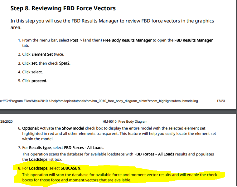
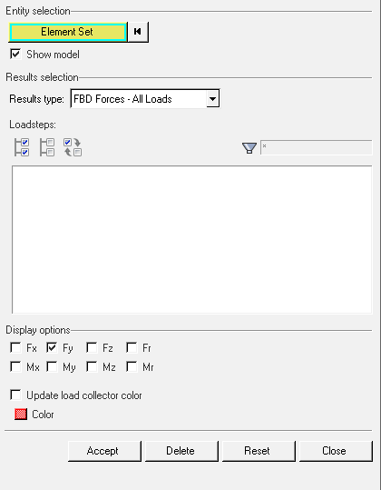
I was following the tutorial HM 9010 up until step 8. When I get to the highlighted step, no loadcases are found. I did skip the first part because I am not interested in creating shear moment/potato plots and started from step 7. The tutorial said I could start from this point. If anyone has suggestions on what I might have missed please let me know.
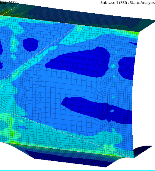
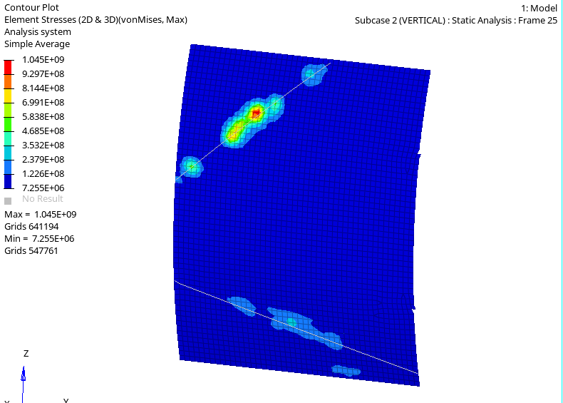
I would also like to know: When performing analysis on a cross section, how can I also enforce the displacements correctly? See the last two pictures attached: The first is a panel in my global model. The second is my panel in the DFEM (.fem files attached). I used the FBD->Forces tool to extract the loads on the section I want, however when I import those forces to my model via BC->Create->Forces->Interpolation, I end up with a ridiculous stress concentration in one part of my model. I'm not sure why this happens, but as far as I can tell there is no way to constrain the model correctly according to the global model. In the global model, all nodes are displaced a certain amount, but in the DFEM the nodes along the edge are forced to be constrained. Is there a way to ensure agreement between the two models?