The Siemens Community Catalyst program was co-created with our community to acknowledge technology leaders who consistently contribute to the Siemens Community. Nominations are accepted on a rolling basis.
Help me to configure ADC Channel for single and double sampling mode ?
and what is the datatype of my adc input block ? and how to debug my adc value and it plot......
I am using TMS20F28035 Piccolo controller board.
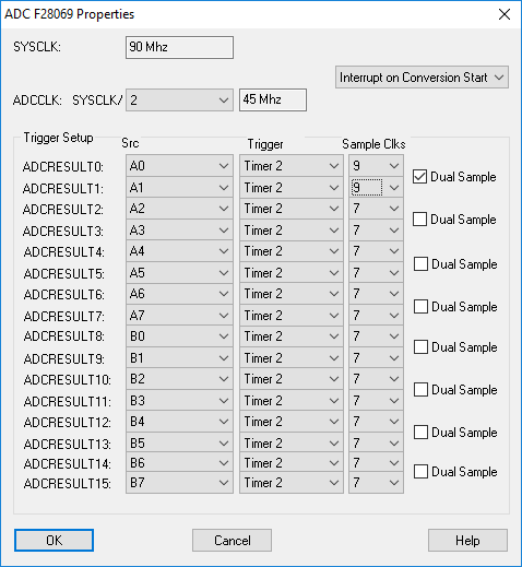
Select Embedded > Piccolo > ADC > ADC Config... and see the screen below.
Each ADC block is associated with an ADC result register. In the dialog screen below, you map analog pins on the chip to result registers. The default mapping is shown below. The trigger source is an event that causes an ADC sample to occur. The timer 2 is used as the RTOS timer, so is a default for the ADC trigger. It is also common to use a PWM to send an ADC SOC (Start Of Conversion) also.
To see an example of plotting ADC values, select Embedded > Examples > Piccolo > ADC > ADCtestF28035
The datatype of the ADC result is fx4.16, this means that it has 4 magnitude bits and 12 fractional bits. Since the ADC result is only 12 bits, the value can range from 0 to 1 (or 0 to .9997 to be precise)
Hi there! What can I do, if this window doesn't show in Altair Embed 2019.0.1?
I have a problem when I use the same ADC. I am using multiple analog inputs at channel A, but all these signals get some interference between them. I tested them one by one, and that is the case. I ran the example ADCtestF28069, and when you have one input on A0, the other inputs also change the value, and if you move to the next A1, the other analog inputs get a scaled value of A1. I also tried on F28379D and have the same problem. Would you explain how to fix this problem? Thank you!
Please use the latest 2022.1 version
https://altairone.com/Marketplace?queryText=embed&app=Embed&tab=Download
Regards,
Girish
Does the issue persists if you input different analog signals to channel A input pins??
All the input pins needs the analog signals to output the correct values. If some of the analog input pins are floating and no input is provided then it outputs some floating values.
Please input analog values to all the pins and check if the issue persists.
Let me know if issue persists and it would be helpful if you attach the test diagram/embed file.