Define BC's in local shell coordinates
Hi all,
How can I define boundary conditions to a node in the local element coordinate system? I have a shell structure (see below) and do not want my BC's in XYZ, but in local u,v,w coordinates.
<?xml version="1.0" encoding="UTF-8"?>
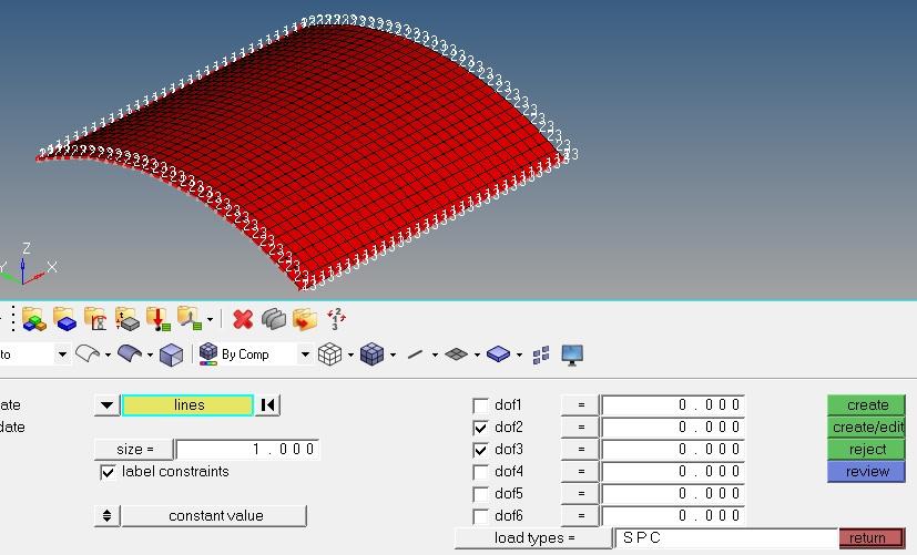
Later, I would love to post-process my results in a coordinate system related to each element as well.
Thanks,
T
Answers
-
Altair Forum User said:
Hi all,
How can I define boundary conditions to a node in the local element coordinate system? I have a shell structure (see below) and do not want my BC's in XYZ, but in local u,v,w coordinates.
Later, I would love to post-process my results in a coordinate system related to each element as well.
Thanks,
T
Hi Tim
BC is defined in displacement system. so you just need to assign the nodes to the local system as displacement system
Enter analysis>system>assign, select nodes and system > set displacement
0 -
Thanks for the answer tinh.
I'm not completely sure how to execute this though:
Step 1 : defining the system. I can define one system manually (systems - create by node reference).
Is there a way to execute this command repetitively though? Every node has a different coordinate system (x, y along axes element, z perpendicular), thus I would have to do this 900 times in my current mesh? (and go to the rest of the procedure 900 times as well...)
Step 2 : analysis>system>assign, select nodes and system > set displacement: works fine (but what did it exactly do?)
Step 3: Where do I now apply my displacements in the newly defined system(s)? I typically go through constraints, but there I don't seem to be able to select the system?
0 -
If your shell has not cylindrical/spherical form, you could write a TCL script to do these task.
0 -
Thanks for the quick anwers, I really appreciate the help!
I'm quite new to the software and getting into TCL scripting seems a bit daunting right now for what I consider as a relatively easy analysis.
So say I stick with cylindrical or spherical shells for now and define a cylindrical system that I then assign to each node: in that case I'm still stuck on step 3: where do I apply my displacements in the newly defined system(s)?
0 -
Altair Forum User said:
Thanks for the quick anwers, I really appreciate the help!
I'm quite new to the software and getting into TCL scripting seems a bit daunting right now for what I consider as a relatively easy analysis.
So say I stick with cylindrical or spherical shells for now and define a cylindrical system that I then assign to each node: in that case I'm still stuck on step 3: where do I apply my displacements in the newly defined system(s)?
Hi Tim
as my comment, BC is define in displacement system so you do not need to select the local system, just create the constraints
dof1~dof6 are dofs of node, node is assigned disp system so the dofs are movements in disp system
0 -
@Tim: Maybe try steps in my screenshot ? Tell us if that can help you.
0 -
Thanks both for your efforts, again, I appreciate it. Unfortunately I'm still not able to define the BC's correctly.
It is very unclear to me how the newly defined coordinate system translates to the axis number and the entire procedure is not transparent. I've been messing with this for hours now and can't get it to work, so I'll try detailing my procedure so hopefully someone might see my maybe obvious error.
The shell is cylindrical (Pi/3 section of a circle situated in YZ plane). I define the origin of the new cylindrical coordinate system at the center of the circle. The 'x-axis' from origin to the top of the shell (along global Z-axis). 'xy-plane', is defined as the YZ plane. Z is defined automatically. This should get me an r t plane in the global YZ plane. I assume r corresponds to DOF1, t to DOF2 and z to DOF3?
I then assign the new system to all nodes the way you described above (BC's>assign>Load Reference System>Nodes>all>set displacement). Then I go to constraints and assign DOF's as below. I aim to restrain r and z on the straight edges (thus select DOF1 and DOF3), r and t on the curved edges (DOF 1 and 2). Results do not make sense. Any ideas?
0 -
Hi,
You are right
dof1 is radial movement
dof2 is tangent movement
dof3 is axial movement
if you fix dof1 dof3 then straight edges cannot move radially and axially
if you fix dof1 dof2 then curved edges cannot move radially and tangent
Does your result follow above comment?
0 -
Thanks so much tinh and Q-NGUYEN-DAI, I managed to get out results that are very similar to the results I expected (nearly the same as defining BC's in XYZ). Results are suddenly slightly asymmetrical though without clear reason, which is weird, but I'll figure that out later. Thanks for the help!
0 -
hi all, for me the purpose is to constrain a set of nodes according to cylindrical coordinate system by allowing only the rotation dof about the cylinder axis and constraining the other two dof's and for this i have created a cylindrical coordinate system with z as the axis of rotation of the cylinder , populated the nodes to be constrained in a entity set and then assigned the nodes in entity set to the created cylindrical coordinate system.
and according to what u have said as my nodes are assigned with the cylindrical coordinate system the dof1,2,and 3 relates to (r,t,z) (radial movement, tangential i.e rotation about z, translation about z) so for my purpose i have to free one rotational dof along the cylinder axis, which means i have to free dof 2 and constrain only dof 1 and 3.
is this what u have stated in the above conversation regarding the topic and am i correct with the releasing of dof2 to allow rotation about z.....
awaiting reply /emoticons/default_smile.png' alt=':)' srcset='/emoticons/smile@2x.png 2x' width='20' height='20'> ...................
0 -
and is the inference of the above conversation is like once a node is been assigned to a particular coordinate system then any constrain given to it will be with respect to the given coordinate system and there is no such place where we can switch over between coordinates like a drop down menu in constraints.
and how to assign a new coordinate system to the whole component,
is it this way
select all nodes in the component and assign them with our desired coordinate system so that the constraints and loads are according to them.
but if that is the case i cant find any (r,t,z) while defining the loading in-terms of force i can find only the (x,y,z) node N1 N2 N3 and Vector but cant find anything like (r,t,z) while assigning load.
so is it like there is no toggling / switching over between coordinates in loaging and constraints.
0 -
DOF 1,2,3 are for translation, 4,5,6 for rotation. Thus, if you defined a new coordinate system with Z along the axis of rotation of your cylinder and you want this rotation to be the only allowed DOF, you should constrain 1,2,3,4 and 5 and keep DOF 6 (rotation around Z) free.
0 -
hi tim thanks for your reply.....
i have taken a solid 3d component and not a shell so the dof i have for my elements are only 3 and i cross verified it by assigning 6 dof's and 3 dof's for the same component but both showed the same results.....
tomo i will try again what you have said me.......
Regards
jeeva.b
0 -
Hi Jeeva,
How about having RBE attached to solid element nodes?
RBEs anyways have 6 DOF. Try this approach.
0 -
hi prakash thanks for your reply.....
are you saying tat i have to form a RBE3 i.e spider element in the middle of the cylinder to the nodes on the surface of cylinder to be constrained and assign the constraints for tat RBE3 by releasing only the DOF6 i.e allowing the rotation along z alone free and constraining other all things.
but then too i feel that, why is it not possible to toggle between coordinates as there in Abaqus or any other FEA package and it might be surely there but am not able to find.
thanks prakash for your effort to find me a alternative i will surely try with RBE3 and will come back soon.........
AND THANKS (TIM, TINH, PRAKASH, RAHUL,etc...) FOR YOUR EFFORT TO REPLY CONTINUOUSLY FOR ALL MY DOUBTS , Admired by the very fast response from U guys /emoticons/default_smile.png' alt=':)' srcset='/emoticons/smile@2x.png 2x' width='20' height='20'> ................
0 -
hi prakash i have tried that RBE3 idea but it is stating that max num of independent nodes for a RBE3 i.e 10000 has been exceeded so am not able to create a RBE3 with respect to a node at center for the whole surface in a single go.....
but i have partitioned the surface and gave two RBE3 elements .and have constrained same as like u have said me...........but will partitioning and giving two RBE3 With respect to a single node will affect my results......
0 -
Jeeva,
For now only 10000 RBE3 can go. In the future version this limit will be increased.
0 -
Hello,
I have some questions about SPC ;
1) I want to define bc on local system , Which system should I use for these dofs, local system or global system?
<?xml version="1.0" encoding="UTF-8"?>
2) My local system is cylindrical coordinate system. Dof1 radial, dof2 tangent and dof3 axial, what are the other dofs, dof4,5,6?
3) Spc work based on cylindrical coordinate system. For example, all direction are constrainded but R and T direction should be movable +/- 1 mm.
How can I apply this condition? Also I want to know how to define this situation on rectangular coordinate system.
Thanks for your reply.
0 -
-