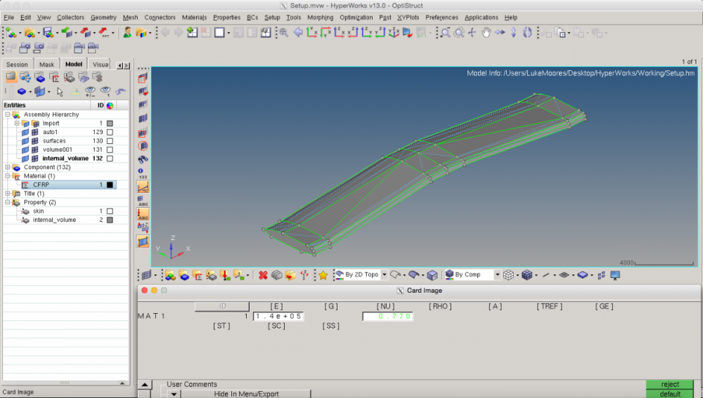
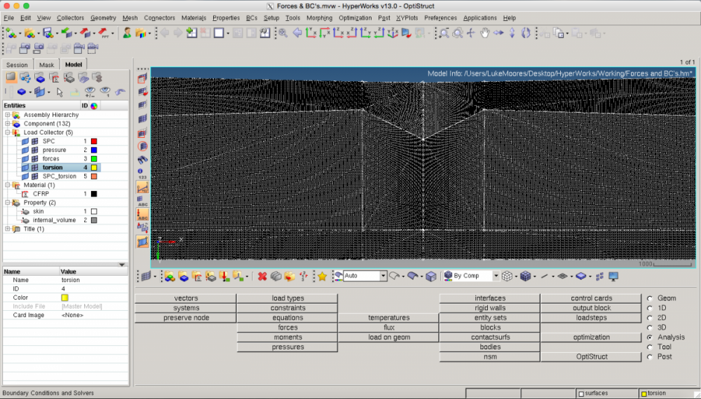
Force, pressure and torsion load cases on a wing
Hi, a bit of a broad question here but I thought I'd ask one long one rather than many short ones when I inevitably get stuck at the next step!
I'm a university student that's new to HyperWorks. I’ve never had any training nor does anyone else at my university know how to use it but I do have access to all the tutorials, however they are obviously simpler than what I’m trying to do so any help would be very much appreciated.
<?xml version="1.0" encoding="UTF-8"?>
Answers
-
In HyperMesh, there is something called ‘loads on geom’ which allows you to associate forces, moments, etc. to lines and surfaces. This means if you update the mesh, the load/node or load/element will update automatically.
Another way to achieve this is to create rigid 1D elements called RBE2s (for applying constraints) or RBE3’s (non rigid for applying loads). Then, you can apply the load to the calculated center of this spider element.
It looks like your mesh may be too refined to run quickly on your desktop/laptop computer. I would recommend using coarse mesh at first until you get it running, then work on refinement.
Did you know you could run this optimization 4 times? :Three times for all three load cases as you say plus an optimization which takes all load cases into consideration. For example, if you have a compliance minimization objective, create a weighted compliance (wcomp) response and activate all three load cases for the optimization run. There is also something new in version 13.0 called multi-model optimization 'multi-model optimization allows running multiple models with common design variables simultaneously'.
Otherwise, I think you could try to think of this as a simple cantilever beam at first and maybe look at some examples of how to load this type of structure. You are doing great so far as a first time user, so keep up the good work!
0 -
Thanks, that helped a lot! I think you might be right about my mesh refinement. It won't allow me to create RBE3's because it says the maximum number of elements (10000) has been exceeded. I'll remesh my part and try again. Can I ask what sort of element size you feel would be appropriate? For reference my part has a width of approximately 4000.
Altair Forum User said:In HyperMesh, there is something called ‘loads on geom’ which allows you to associate forces, moments, etc. to lines and surfaces. This means if you update the mesh, the load/node or load/element will update automatically.
Another way to achieve this is to create rigid 1D elements called RBE2s (for applying constraints) or RBE3’s (non rigid for applying loads). Then, you can apply the load to the calculated center of this spider element.
It looks like your mesh may be too refined to run quickly on your desktop/laptop computer. I would recommend using coarse mesh at first until you get it running, then work on refinement.
Did you know you could run this optimization 4 times? :Three times for all three load cases as you say plus an optimization which takes all load cases into consideration. For example, if you have a compliance minimization objective, create a weighted compliance (wcomp) response and activate all three load cases for the optimization run. There is also something new in version 13.0 called multi-model optimization 'multi-model optimization allows running multiple models with common design variables simultaneously'.
Otherwise, I think you could try to think of this as a simple cantilever beam at first and maybe look at some examples of how to load this type of structure. You are doing great so far as a first time user, so keep up the good work!
0 -
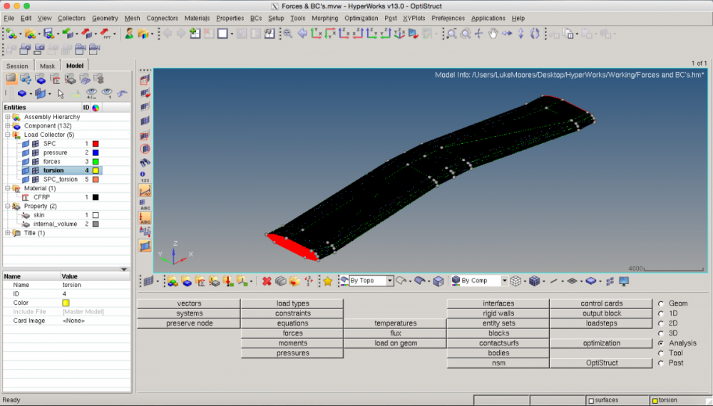
In case anyone else has a similar issue, the above advice worked. I made a coarser mesh and created RBE3 nodes to apply the torsion and forces. I'm still yet to apply the pressure loads so would appreciate any advice anyone could give me as to the best way to do it. Attached are screenshots that someone in a similar position to me may find useful. One end of the wing is fixed and the other has a moment applied to it via the RBE3.
0 -
Hi,
You can apply pressure on solid element using Pload4 card for Optistruct solver.Select element and define nodes on face of phase where you want to apply load.
Even you convert pressure loading to force and applying using same rigid concept.Please refer attached thumbnail.
Regards
Rahul R
0 -
Luke, where are your pressure loads going to come from? Also, are you looking at optimizing the skin, the core structure, or both. What is the core material?
0 -
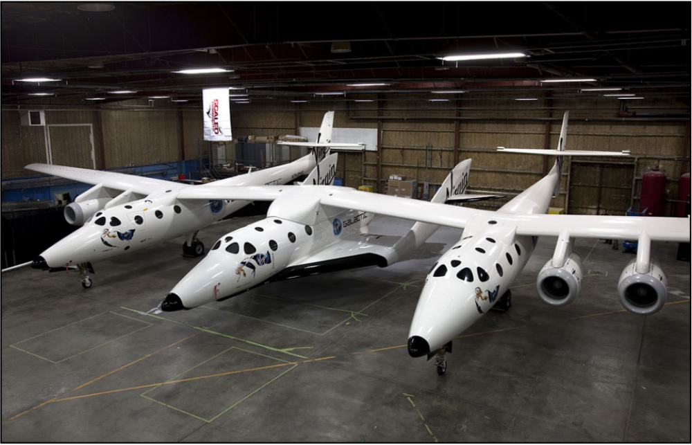
The pressure loads are there to simulate the aerodynamic loading on the wing. For this particular wing I'm not actually expecting it to make that much difference to the structure as the payload forces and torsion about the wing are going to be much more structurally demanding. The primary objective for the optimisation is therefore to support the force and moment loads in the most efficient way with the pressure load being more there to make sure that the suggested material distribution doesn't have any huge voids near the skin which would cause it to buckle. So in that regard the magnitude of the pressures is less important than the magnitude of the other loads. I don't want to optimise the skin, in fact I want to set it as non-design space to prevent the optimiser from suggesting any non-sensical holes in it. The entire wing (the entire aircraft in fact) is made from carbon fibre reinforced polymer. I've also set the thickness of the shell (the skin) to 140mm. Also, please bear in mind that my project really is just to get the concept of the internal wing structure, I'm aware that I'm making some huge approximations and that if I wanted to design this structure for real it would be far beyond the scope of a third year university project!
0 -
To expand on what I want to do..... I want to apply patches of pressure on the surface of the part acting in the normal direction to the surfaces. I want a total of 12 patches of constant pressure, 6 on the upper surface and 6 on the lower surface (see attached table). The patches need to be rectangular and each one needs to cover 1/6th of the width of the wing (chord) and it's entire length. The patches are not geometrically the same size as the surfaces that the wing's skin is made of so I'm trying to select the area by elements. It's obviously not feasible to select the elements individually and I've tried to select them by window but then it also selects the elements on the lower / side surfaces. Any tips would be appreciated!
Also, just to clarify for anyone who isn't an aerospace engineer, the pressure distribution I'm approximating is the one in the attached diagram.
<?xml version="1.0" encoding="UTF-8"?>
0