Error #153 modeling suspension

Altair Forum User
Altair Forum User
Altair Employee
edited October 2020 in Community Q&A

Good morning,


at the moment I'm doing some tests for an upcoming optimization. I use HM 14.0 with Optistruct.

I want to simulate a simplified suspension.If I model the suspension rods with CONROD-Elements, the following error message appears:


*** ERROR # 153 ***
 Exactly zero pivoting encountered during Numerical Factorization;
 the model may have rigid body mode.
  Solver error no. =   -503 
        spc set id = 1 
             index =      1 
 Possible reasons are:
 1) insufficiently constrained model,
 2) having rigid body mechanisms within the model,
 3) extremely ill-conditioned rigid element sets,
 4) extremely thin shells (as used for skinning) that have MID2/MID3,
 5) gap elements with extremely high stiffness (KA, especially KT or MU).
 Check the model and rerun the problem.
 (MECHCHECK may be used to find the rigid body modes.  To do so,
  change the input to be an eigenvalue analysis and add MECHCHECK.)
 (WARNING: results obtained with MECHCHECK cannot be used because
          the model is changed internally.)
 This error was detected in subroutine bcsmtxfct.


If I turn MECHCHECK on, the max. displacement is 0.008061 mm. 

When I replace the CONROD Elements with nearly stiff CBEAM Elements, the error message disappears. The max. displacement is 0.00769227 mm. 


To my knowledge, the suspension rods are just tension and compression rods.


Could you help me, why I get the error message? I attached the file.


Best regards,

Kai


<?xml version="1.0" encoding="UTF-8"?>Unbenannt1.PNG
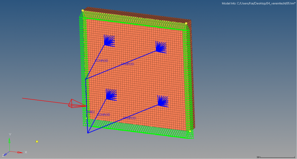
 

Answers

  • Altair Forum User
    Altair Forum User
    Altair Employee
    edited August 2017

    Hi,


    Thank you for sharing file. I will check and update to you soon 

  • Altair Forum User
    Altair Forum User
    Altair Employee
    edited August 2017

    Hi Kai,


    Is there a reason for having MCHECK?


    I think the problem is coming from the element type as ROD elements are suitable for transverse load but beam element does support transverse load.


    In your model the load going to rod looks like a transverse load which is perpendicular to rod axis.

  • Altair Forum User
    Altair Forum User
    Altair Employee
    edited August 2017

    Hi Prakash,


    thank you for your reply.

    MCHECK is on to get a result for the displacement. Otherwise I would just get the error message.

    OK, so I get transverse load, which does not work with ROD Elements, because of the shared nodes between the ROD-Elements and the RBE-Elements. But actually the shared nodes should work like a ball joint, like the one in the picture. To my knowledge this ball joint should prevent any transverse loads, so that I could work with the CONROD Elements.


    Do you have an idea how I should model this type of connection? 


    Best regards,

    Kai


    <?xml version="1.0" encoding="UTF-8"?>Unbenannt.PNG

  • Altair Forum User
    Altair Forum User
    Altair Employee
    edited August 2017

    Hi,


    All dofs of RBE are connected to Rod elements and no Dofs are released to make it a ball joint. You can use Joints>>FE>> Ball joint to create FE joints. 

  • Altair Forum User
    Altair Forum User
    Altair Employee
    edited August 2017

    Thank you Prakash. Unfortunately Joints just seem to work with MBS.

    I sent another example with the same error. The RBE2 Elements transfer no rotations around z, so that they should work like a revolute joint. 

    Could you explain me, why I keep getting the #153 error?


  • gopal_rathore
    gopal_rathore Altair Community Member
    edited August 2017

    Hi,

    You can try making such ball joint making a spring between two rbe2 elements and then making stiffness high for translation and zero for the rotational directions as per the assigned coordinate systems to spring


  • Altair Forum User
    Altair Forum User
    Altair Employee
    edited August 2017

    Hi,

    You can try making such ball joint making a spring between two rbe2 elements and then making stiffness high for translation and zero for the rotational directions as per the assigned coordinate systems to spring


    Thank you gopal_rathore, but I think my problem is due to the limits of a linear static simulation. Maybe I have an incorrect understanding of it?


    I placed RBE2 Elements (DOF: 1,2,3) between two coincident nodes (see the blue circles), which should allow rotations.

    Do you see a reason why this model results in an error?


    *** ERROR # 723 ***
     An invalid rigid element.
     This RBE2 is not connected with any structural element.
         RBE2 element id = 8
     independent grid id = 4
     Note: If this rigid element is also connected with other rigid elements,
     then this error means that there is rigid body mode or mechanism remained
     in this rigid element chain due to lack of connected structural elements.

    <?xml version="1.0" encoding="UTF-8"?>Unbenannt2.PNG

  • gopal_rathore
    gopal_rathore Altair Community Member
    edited August 2017

    Hi,

    As per my understanding , we have created the below given scenario at the coincident nodes making a rigid chain.

    Thus, when we apply a force as shown and consider no  dof applied now., a rigid mode should come with certain displacement. Now when we apply, the dof at other end and apply force , it violates the functioning of rbe2. 

    Now if we can add springs in the model at concident node and dof end which acts as a structural element , it might work.

    <?xml version="1.0" encoding="UTF-8"?>rbe2_connections.png

  • Altair Forum User
    Altair Forum User
    Altair Employee
    edited August 2017

    Hi @Kaihes


    Starting from 2017.1 joints can be used for FE modelling. You can also make joints with RBEs as @gopal_rathore posted or using CBEAM pin flags.

  • Altair Forum User
    Altair Forum User
    Altair Employee
    edited August 2017

    Okay thank you all. I reduced the values of the spring stiffness and the elastic modulus in the following example and it finally works. Thank you all for your help ;-)

    @Prakash Pagadala Is there a highest value for the elastic modulus or a specific value which is assumed to be 'stiff'?


    Best regards,

    Kai


    <?xml version="1.0" encoding="UTF-8"?>Unbenannt4.PNG

  • Altair Forum User
    Altair Forum User
    Altair Employee
    edited August 2017

    Hi Kai,


    Sometimes we randomly use very high E (in the order of E11-12) and found no issues with limit.