Spring connection between two componentes

Altair Forum User
Altair Forum User
Altair Employee
edited October 2020 in Community Q&A

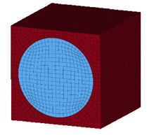
I'm modeling a representative volume element that it's basicaly made by a cylinder inserted into a cube. I need to make a spring contact between this two parts, changing the spring stiffness i want to analyse the perfect and the imperfect contact. Anybody has a tip to build this model with spring elements (CBUSH) only in the common nodes between the cylinder and the rest of the cube? Those spring elements need to be at a cylindric system.


I have something like this:


<?xml version="1.0" encoding="UTF-8"?>Capture.JPG
Answers

  • tinh
    tinh Altair Community Member
    edited August 2017

    Hi,

    create face elems of the two comps, then use 1d>linear 1d to create 'spring' between 2 contact sides

    switch spring to cbush and apply CID as you need

    example: 

    Capture.PNG.ffed9965337242374ef0805f5e5d7374.PNG

    Unable to find an attachment - read this blog

  • Altair Forum User
    Altair Forum User
    Altair Employee
    edited August 2017

    You can use either 1D linear to create or use connectors>> Spot weld>> Springs and update to CBUSH with CID

  • Altair Forum User
    Altair Forum User
    Altair Employee
    edited August 2017

    Ok, i'll try that and give you guys a feedback! Thank you.

  • Altair Forum User
    Altair Forum User
    Altair Employee
    edited September 2017

    Hi together,


    i try to achieve the same thing. I create the face elements over faces, find faces and put them in two new components. Afterwards i try to connect them over linear 1D. Now I get the error: 2 meshs elem orders differ. Is there anything else i need to consider?


    After this step, do i have to delete the two face meshes created?


    Thanks for your help!


    Sebastian

  • Altair Forum User
    Altair Forum User
    Altair Employee
    edited October 2017

    HI,


    Do you get this error during analysis or during modelling?


    I don't see a point for having face elements. 

  • Rahul Rajan_21763
    Rahul Rajan_21763 New Altair Community Member
    edited October 2017

    To use 1d linear.you should have same no of element on both faces & make sure you give proper alignment.

  • Altair Forum User
    Altair Forum User
    Altair Employee
    edited October 2017

    I tried to use the model created by tinh in the earlier post. () I get the error during the modelling.


    I extracted the face elements from both components and tried to connect them over 1d linear. 


    As Input i selected: from (face elems component number one) to (face elems components number two)


    When i press the create button i receive this error message. (2 meshs elem orders differ)


    Is there anything I am doing wrong?


    Is there a need to define the allignment or the density?


    Thank you for your help!


    Sebastian

    Unable to find an attachment - read this blog

  • tinh
    tinh Altair Community Member
    edited October 2017

    Maybe you were wrong in n1n2n3 selection

    3nodes must be on corresponding elems

  • Altair Forum User
    Altair Forum User
    Altair Employee
    edited October 2017

    Hi,


    Did you extract face elements of the elements which are part of hole on blue component?


    Also check the  alignment as @tinh suggested.


    Another workaround (You don't have to create face elements)  is to use Connectors>> Spot>> Spring. Select the nodes and components and create CELAS1 elements. Goto connectors browser and delete connectors (not connectors and FE)


    Now go to springs panel>> update>> change element type to CBUSH>> select all CLEAS1 elements>> update element type.


  • Altair Forum User
    Altair Forum User
    Altair Employee
    edited October 2017

    Thank you! It worked.