Roll over analysis
Hi,
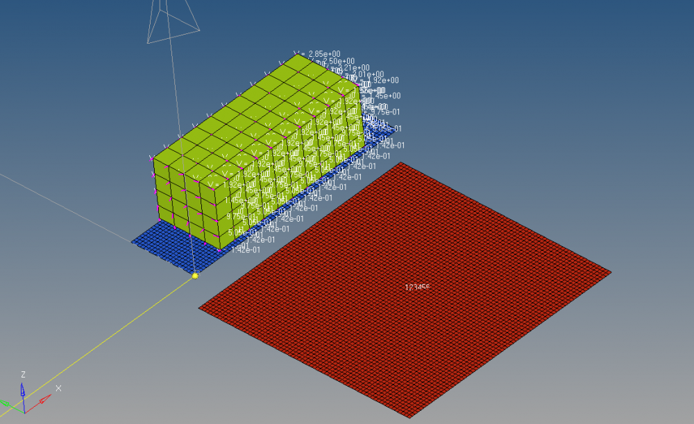
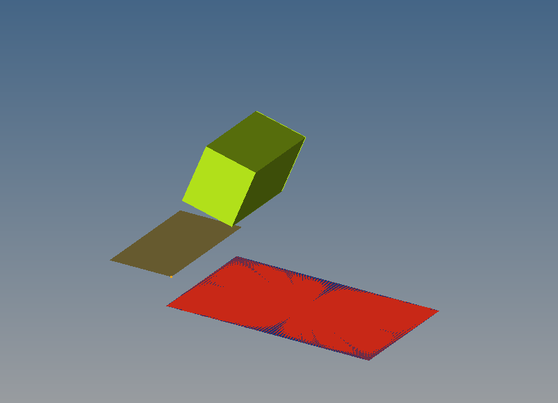
I'm new to radioss. I'm carrying out roll over analysis on box as shown in attached image. i've assigned initial velocity along axis and got the box roatating, the problem i'm facing here is the box is being thrown upward and its not falling on the base.do i need to assign gravity? if so how?
Answers
-
Hi,
From the BCs Manager you can create the gravity load. Create a function for the same, select the direction and apply it to all the nodes in the model.
Please go through RD-3597: Cell Phone Drop Test using HyperMesh tutorial in the Help Menu which shows applying gravity load in the model.For /INIVEL/AXIS load collector make sure the axis is properly selected. Please take a screenshot of the /INIVEL/AXIS card and upload.
If you still face any issues please share the model file through the secure dropbox link.
0 -
Hi,
It seems that the blue colour platform needs to be rotated until the box gets unstable and rolls over. Is this the case you are studying ?
0 -
Altair Forum User said:
Hi,
It seems that the blue colour platform needs to be rotated until the box gets unstable and rolls over. Is this the case you are studying ?
yes, i tried doing that by applying rotational velocity to the platform but it didn't help. so i applied rotational velocity to box as mentioned in this http://www.altairatc.com/india/previous-events/2012/papers-2012/RNL-A-07_Rollover_Analysis_of_Bus_Body_Structure_Volvo.pdf . as there is no proper tutorial kind for this, i'm trying all methods to achieve rollover. if you can help me in achieving a tilt please provide some steps to follow.
0 -
Hi,
In the paper mentioned we can see that the bus is already in a tilted condition and so they applied the rotational velocity to the bus.
Can you please share the model file so that we can check and update you.
0 -
Hi Guru,
As George said, the bus is already in tilted position.
In your case, you can rotate the platform and the box to a certain angle based on the cg location to find the unstable angle. The you can apply gravity for free fall .
Second method is you can completely tilt the box till a position just 2-3 mm above ground and apply a calculated angular velocity using INVEL_AXIS collector along with gravity..This methodology is used in Volvo bus paper.
0 -
-
Hi,
Negative error % refers to the energy being absorbed in the system , this would happen as the body is under load conditions The error % needs to be minimal. What values are you getting?
0 -
Hi,
The energy error percentage is the parameter that checks the energy conservation during each numerical cycle. Negative Energy Error represents the energy dissipated from the system. This can be damping from many sources including plastic deformation and hourglass energy. If you are not expecting high plastic deformation in the problem, then hourglass energy can be a reason. Only user can decide the acceptable range with negative energy error.
0 -
when applying initial velocity by axis for a taurus car model, should i apply velocity to whole model including connections or only car model??
0 -
Hi,
Apply load to the whole model.
You can also watch this webinar http://www.altairuniversity.com/learning-library/9-prodecure-to-apply-initial_velocity-around-an-axis/ which shows procedure to apply Initial_velocity around an axis.
0 -
** ERROR IN HIERARCHY REFERENCE
DESCRIPTION :
-- NODE GROUP ID : 2014993
-- comp TITLE : PART
REFERENCE TO UNEXISTING ID=8101620what does this mean?
0 -
Hi,
Ensure that PART card image is assigned to the components and material and property cards are assigned.
Also recommend you to run the Model Checker (Tools>Model Checker >RADIOSSBlock) which will list out the errors/warnings in the model.
If the issue persist, please share the model file.
0 -
-
Hi,
There is no need to define an interface between the rigid wall and component. But,ensure that slave nodes has been added in the rigid wall card.
In the rigid wall card, user can review the RWALL defined and thereby we can ensure that it is correctly defined.
0 -
Hi Guru,
You can edit rigid wall to set various parameters like friction, contact behaviour like slide etc. For more details , refer help file.
0 -
what is the procedure to find stability angle of bus?? can i find using radioss or anyother altair product??
0 -
Hi,
You can get max. stability angle by simply rotating the bus and checking the angle when the CG comes in line with rotation axis. This does not require any software also and basic trigonometry will work for you.
0 -
Hi
Can you please guide me how to define rotation on the plate as shown in below picture. As shown in picture the ball has to rotate with some force how is it possible. This analysis is Burnishing process. If you have any example please share me it will help full for me.
Thanks
0 -
hi,
The plate will be constrained first from the bottom . Make ball as rbody and apply imposed velocity about the ball centre axis. Also constraint the master node of rbody in all directions except free for translation in the direction of motion and rotation about the axis of ball. Try this and let us know if it works.
Also do you have surface data over the plate i.e irregularities which would be leveled by the burnishing process.
0 -
Thanks gopal,
I will try it and let you know.I will share the model if its not works. Currently i don t have any data. DO we need to require the data must and should ?
Regards
Dinesh
0 -
Altair Forum User said:
Thanks gopal,
I will try it and let you know.I will share the model if its not works. Currently i don t have any data. DO we need to require the data must and should ?
Regards
Dinesh
Hi,
As burnishing , levels the surface of the plate by removing the irregularities, a profile of the top surface might be required. I am not sure for it as of now.
What exactly do you want as output from the simulation, it would depend on that also.
0 -
Hi gopal,
I have done modelling and setup the model has you said but i am not getting any movement. Can you please check once so that it will easy for to check it i am attaching the model.
0