Simulate bolt constraint

Altair Forum User
Altair Forum User
Altair Employee
edited October 2020 in Community Q&A

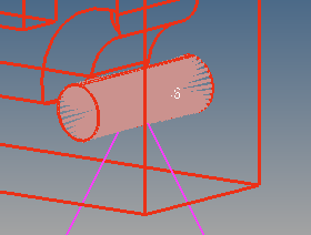
I want to simulate in Hypermesh the constraint, in a cilinder, due to the presence of bolts. To do this I created a geometrical node in center of the cilinder with a constraint of all 6 DOF, and then used rigid element (RBE2) to connect the node with all nodes in the surface of the cilinder, as shown in this picture:

<?xml version="1.0" encoding="UTF-8"?>post-37131-0-12631300-1432997870_thumb.p
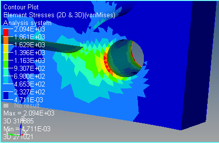
results in Hyperview show a very strong vonMises stress in the external part of the cilinder. I think this result does not represent reality because the stress should be uniform along the bolt.

 <?xml version="1.0" encoding="UTF-8"?>post-37131-0-40080700-1432998307_thumb.p
there are other way to modeliza the interaction between structure and bolts?

thanks

Tagged:

Answers

  • Altair Forum User
    Altair Forum User
    Altair Employee
    edited June 2015

    Hi Darioaresta,


    When there is a change or deviation in the body, more stress will be seen at that areas (Stress concetration areas).


    You can exclude a row of elements around the hole and post process for results.


    Also, since RBE2s are stiffer elements and will not allows nodes to move relatively. Instead use RBE3 elements.

  • RAMGANESH
    RAMGANESH Altair Community Member
    edited November 2020

    Dear Prakash,


    Can we generate spring connectors and apply the stiffness of the bolt instead of RBE2 & RBE3 elements???

    Unable to find an attachment - read this blog