The Siemens Community Catalyst program was co-created with our community to acknowledge technology leaders who consistently contribute to the Siemens Community. Nominations are accepted on a rolling basis.
Electric and magnetic symmetry can be used to reduce runtime and memory requirements in FEKO, as discussed below. It is applicable to the MoM and all the hybrid techniques where MoM is involved (such as MoM/PO and MoM/FEM), but cannot be used in conjunction with the MLFMM.
Electromagnetic field problems can possess three types of planar symmetry: geometric, electric and magnetic. The type of symmetry is defined by the geometric properties of the structure and sources.
Geometric Symmetry
In this case the geometry of the structure must be symmetric with respect to the symmetry plane, while the sources may be arbitrarily located. Such a setup generally leads to non-symmetric current distributions on the structure.
Electric Symmetry
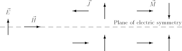
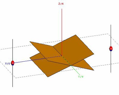
In the case of an electric symmetry plane, not only must geometric symmetry hold, but additional requirements also have to be met by the sources. Figure 1 shows these requirements. The electric current density must be anti-symmetric and the magnetic current density symmetric. A physical interpretation of an electric symmetry plane is a plane which can be replaced by a PEC wall without changing the field distribution. The tangential component of the electric field and the normal component of the magnetic field thus disappear at such a plane.
Figure 1: Requirements on sources for a plane of electric symmetry.
Magnetic Symmetry
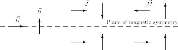
In the case of a magnetic symmetry plane, geometric symmetry must again hold, again with additional requirements on the sources, but different from the electric case. Figure 2 shows these requirements. The electric current density must be symmetric and the magnetic current density anti-symmetric. A physical interpretation of a magnetic symmetry plane is a plane which can be replaced by a PMC wall without changing the field distribution. The normal component of the electric field and the tangential component of the magnetic field thus disappear at such a plane.
Figure 2: Requirements on sources for a plane of magnetic symmetry.
When using numerical methods to solve electromagnetic field problems, symmetry may be exploited to reduce computational costs in terms of runtime and memory requirements.
In FEKO, the three types of symmetry planes discussed above result in the followin benefits:
Clearly, the benefits of symmetry can be significant.
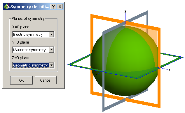
In CADFEKO symmetry is considered a property of the model. Symmetry planes are defined via the Define symmetry planes dialog under Model in the main menu (see Figure 3). The coordinate planes x = 0 (yz plane), y = 0 (zx plane) and z = 0 (xy plane) may be defined as planes of symmetry (geometric, electric or magnetic). There is no restriction on assigning symmetry properties to more than one of the coordinate planes, in which case the computational benefits are compounded. CADFEKO indicates the current symmetry of the model in the 3D view, as shown in Figure 3. A preview is always shown while the Symmetry planes dialog is open. The display of symmetry planes may be deactivated by toggling the Show symmetry planes icon. The symmetry display is coloured according to the symmetry type (green for geometric symmetry, orange for electric symmetry and grey for magnetic symmetry).
Figure 3: Symmetry planes being displayed in CADFEKO and the symmetry definition dialog.
When applying symmetry in CADFEKO, the whole symmetric model should be created, including ports, sources, loads and so forth. The fact that it is not necessary to only create a section of the model makes it very easy to switch between a solution that employs symmetry and one that does not, or adjust the symmetry properties of the model without any geometry or mesh modifications. Symmetry planes must be set before meshing, though the type of symmetry may possibly be altered afterwards. During meshing CADFEKO will validate that the geometry to be meshed does indeed adhere to the specified model symmetry (both geometric symmetry as well as symmetry of excitation and loads where magnetic or electric symmetry is concerned). If the model is found not to adhere to the specified type of symmetry, CADFEKO will abort the meshing process and provide a list of objects in the model that break the symmetry.
Finally, note the following:
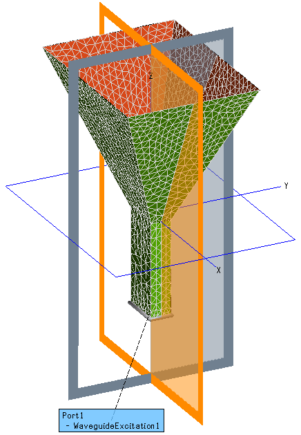
In Figure 4 a horn antenna is shown, excited with a dominant mode, rectangular waveguide port (a full description of the problem can be found in the FEKO Example Guide). The plane z=0 is clearly not a geometric symmetry plane, while the other two planes are. The plane y=0 is a plane of electric symmetry, since the incident wave is electrically polarized in the y-direction and this is already a geometric symmetry. The plane x=0 is a plane of magnetic symmetry, since the incident magnetic field is normal to this plane and the associated electric field is tangential to it, together with the fact that this is also a geometric symmetry plane.
The symmetry properties of the antenna are as follows:
Figure 4: Electric and magnetic planes of symmetry of the horn antenna problem.
The problem is now solved using the MoM, with various combinations of symmetry planes, with the computational costs noted. No near or far field requests were made, in order to isolate the impact of symmetry on computational cost as much as possible. The results are as follows:
Note the following:
Consider two dipoles and a cornered PEC plate between the dipoles.
If symmetry is to be applied, the first consideration is whether there is geometric symmetry. There are 3 planes of symmetry, at X=0, Y=0 and Z=0, so without any further considerations, we can at least set geometric symmetry on these 3 planes.
The next question then is if these geometric symmetry planes can be set to electric or magnetic symmetry (to exploit the saving in computational resources). The sources will dictate the setting of symmetry. Consider the following sets of sources and their respective symmetry settings:
For Case 1 there is no symmetry in the sources and all symmetry planes are set to geometric symmetry only.
For Case 2 there is perfect symmetry in the sources. We consider therefore the fields of the two dipoles using the definitions from Figure 1 and Figure 2. For the Z=0 plane the doughnut shaped electric fields will be normal to the Z=0 plane and therefore non-zero. There will not be a tangential component of the electric field at the Z=0 plane (the dipoles are vertically polarised). Therefore for the Z=0 plane, we have electric symmetry. For the Y=0 plane there will be a tangential component of the electric field in this plane but not a tangential magnetic field component (the magnetic fields will be normal to the Y=0 plane). Therefore for the Y=0 plane, we have magnetic symmetry.
For the X=0 plane, consider the combined electric fields of each dipole at this plane. The fields are vertically polarised and will each be tangential and in the same direction at the X=0 plane at any point in time. There is therefore a large tangential component of the electric fields at the X=0 plane. We therefore cannot set electric symmetry. The magnetic fields at any point in time will be tangential to this plane too, but in opposite directions (and same magnitudes), therefore they cancel and we have zero tangential magnetic fields at this plane. We can therefore set magnetic symmetry on the X=0 plane.
Note that if the phases of the sources differed by 180 degrees, by similar reasoning we would have had electric symmetry on the X=0 plane.
In FEKO, the benefits of symmetry can be very significant. However, since symmetry cannot be exploited together with the MLFMM, the user should verify which of these features yield the largest reduction in computational cost and then only retain that feature in their model. The MLFMM is highly suited to structures of multiple wavelengths, but is not as beneficial in cases of small structures with very complex geometry. Should the latter structures be symmetric, they constitute a prime example of a problem class where symmetry can be very beneficial. When special Green functions are employed (planar and spherically layered media) the MLFMM is also not applicable. With special Green functions, symmetry should always be exploited when computational cost becomes an issue.
Also have a look at
I have so many faces so due to that i cont assign the windscreen on that how can i do the single face