AcuConsole Fan Rotation

Altair Forum User
Altair Forum User
Altair Employee
edited October 2020 in Community Q&A

Hello everyone,


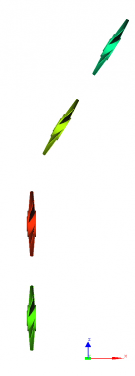
I am trying to simulate axial fans located behind the radiator of a semi truck in AcuConsole. I have three sets of fans in which one set has its axis similar to global coordinate system whereas the other two sets of fans have their rotation axis inclined to the global coordinate axis. I have tried to run the simulation but I have been experiencing divergence issues. I figured out the reason for this and it appears to be with the axis of rotation of the inclined set of fans. 


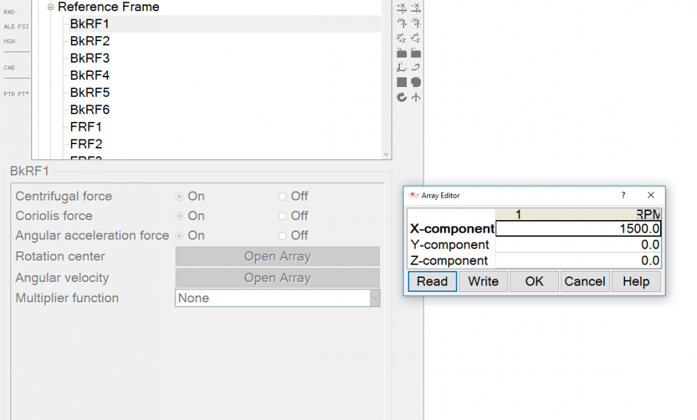
Till now, I have been creating a reference frame where i specify the rotation center as the center of rotation for the fan and then specify the RPM using the angular velocity option along one component (X, Y or Z). This I think is wrong. Could somebody help me out with specifying the correct axis of rotation for the inclined set of fans?


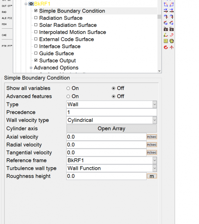
Should I specify different X, Y & Z components in the angular velocity section of the reference frame for the fans or should I change the 'Wall Velocity type' to 'Cylindrical' in the 'surfaces' tab, specify the cylindrical axis in AcuConsole? In that case, I was wondering if I should keep the Radial. Axial & Tangential velocity sections to 0.0 m/sec or give them a value?


I have attached some screenshots which may help for reference.


Thanks,

Yatish.

<?xml version="1.0" encoding="UTF-8"?>Reference Frame.PNG
<?xml version="1.0" encoding="UTF-8"?>Wall Velocity Type.PNG

<?xml version="1.0" encoding="UTF-8"?>Fans.PNG

Tagged:

Answers

  • ydigit
    ydigit
    Altair Employee
    edited April 2018

    Someone from Altair US Support will contact you offline and get your query sorted out.

  • acupro
    acupro
    Altair Employee
    edited April 2018

    It is still correct to use the Reference Frame approach, without a cylindrical wall velocity, such that the velocity increases moving radially away from the center.  The Rotation Center is any point on the axis of rotation.  You then need to define the Angular Velocity components such that the resultant magnitude and sense of rotation are correct based on the right-hand rule.

  • Altair Forum User
    Altair Forum User
    Altair Employee
    edited April 2018

    Thanks for the inputs @ydigit and @acupro .


    I just want to clarify that I have the right understanding. If the rotation axis of the fan makes an angle of 58 degrees with the global x axis and 32 degrees about the z axis (inclined about y axis as seen in last figure), will the angular velocity components in that case be as follows?:


    X Component: RPM*cos(58)

    Y Component: 0

    Z-Component: RPM*sin(32)


    Thanks,

    Yatish

  • acupro
    acupro
    Altair Employee
    edited April 2018

    X would probably be RPM*cos(58); Z would probably be RPM*cos(32) = RPM*sin(58)  -  rather than sin(32)

    But you can check the results after a few time steps.  Look at velocity contours on the fan blades surfaces and you should see zero at the center with the magnitude increasing with increasing radius.  Vectors on the surfaces (or velocity components contours) will help understand sense of rotation.

  • Altair Forum User
    Altair Forum User
    Altair Employee
    edited April 2018

    Thanks for the info @acupro.


    So I have tried to simulate simplified models by isolating the fans to better understand the rotation and I still seem to have some issues.

    I have attached the velocity magnitude contours on the surface of a standard fan and a fan with an inclined axis.

    As you can see, the contour on the standard (non inclined fan) makes sense wherein the magnitude increases from the hub to the tip. Whereas with the inclined fan, that is not the case. 


    I have used the same boundary conditions for both the cases and for the inclined fan, I calculated the Angular Velocity components as follows:


    The fan makes an angle of 40 degrees with the x axis and 50 degrees with the global z axis.

    X component: RPM*cos(40 deg) = 4000*cos(40 deg)

    Y component: 0 (rotation about y axis)

    Z component: RPM*cos(50 deg) = 4000*cos(50 deg)


    I have tried several other approaches, for example RPM/cos 40 and RPM/cos50 however, the rotation still doesn't occur about the right axis.


    I would appreciate any help on how to fix this issue. I have been stuck with this for over a week now.


    Thanks,

    Yatish

    <?xml version="1.0" encoding="UTF-8"?>StandardFan.PNG

    <?xml version="1.0" encoding="UTF-8"?>InclinedFan.PNG

    <?xml version="1.0" encoding="UTF-8"?>Angular Velocity Components.PNG

  • Altair Forum User
    Altair Forum User
    Altair Employee
    edited April 2018

    Hi,


    i am also interested in the solution of the problem. Can anyone explain how to define the angular velocity components?

    Thanks in advance.


  • acupro
    acupro
    Altair Employee
    edited May 2018

    Can you include a snapshot showing the fan plus the global/orientation axis?

  • acupro
    acupro
    Altair Employee
    edited May 2018

    I built a small example.  The center of rotation is at the origin.  The rotation axis is normal to the Y-axis (so no rotation about the Y-axis), and at 40-deg to the X-axis (50-deg to the Z-axis).  I'm using 100 RPM resultant angular velocity.  The blade radius is 0.15 m (to the center) so the max velocity should be about 1.57 m/s.  I've attached images showing the reference frame angular velocity setup and the results.

    Rotor_RF_Setup.jpg.d2f8e67d07d70147142d6f5e7ea008e9.jpgRotor_Results.jpg.efbe842ab2b3902ee7c97e9974a1ee7a.jpg

  • acupro
    acupro
    Altair Employee
    edited May 2018

    I'm guessing that you may need to use a negative sign for one of your X or Z components - or both - to make sure the resultant vector is pointing the correct direction for the orientation of the fan.  This is based on the right-hand rule.

  • Altair Forum User
    Altair Forum User
    Altair Employee
    edited May 2018

    @acupro Thanks for your valuable insights and recommendations. 


    It looks like I had to use a -ve sign for the Z-component as you have mentioned. That fixed the rotation issue I have been facing.


  • Altair Forum User
    Altair Forum User
    Altair Employee
    edited June 2018

    Hi @Yatish Chandra,


    how could you define the center of rotation?  For a non-simplified fan geometry it can be confusing to define it, if the fan is rotated not only in one axis, rather in two for example.


  • Altair Forum User
    Altair Forum User
    Altair Employee
    edited June 2018


    Hi @Yatish Chandra,


    how could you define the center of rotation?  For a non-simplified fan geometry it can be confusing to define it, if the fan is rotated not only in one axis, rather in two for example.


    @raskolnikov You'll have to calculate the components of rotation for the different axis using = RPM*cos(Angle) as explained above.

    Then, based on the orientation of the axes, make sure you specify the correct sign conventions, which is really important.


    In my case, based on the figures attached above, the components were somewhat as follows:


    x: RPM*cos(Angle)

    y: 0.0

    z: -(RPM*cos(Angle)).


    The -ve sign for the z component made all the difference.

  • Altair Forum User
    Altair Forum User
    Altair Employee
    edited June 2018

    Hi @Yatish Chandra,


    it is OK. I understood already it, but my question was how to define the center of rotation. I mean you have to give a exact point for it.

    If you take random nodes/points (center of rotation) on the rotation vector axis, you can take different results for different points. Where is the center of rotation as a point?

  • Altair Forum User
    Altair Forum User
    Altair Employee
    edited June 2018

    @raskolnikov


    I used my CAD file to determine the cartesian co-ordinates for the center of rotation and then used that in AcuConsole. I think that is the easiest way. It was basically the center point on the fan hub which was used as the point of rotation.


    There is a way to do it on AcuConsole too. You can right click on 'Models' > Query > and then use some of the options there to figure out the center of rotation.


    I hope this answers your query.

  • acupro
    acupro
    Altair Employee
    edited June 2018

    The center of rotation can be any point which lies on the axis of rotation.

  • Altair Forum User
    Altair Forum User
    Altair Employee
    edited June 2018

    Hi,

    I thought also that this could be any point on the defined axis. Really interesting, because i get different results for different points on the rotation axis. So i will check of this again. 

    Thanks

  • acupro
    acupro
    Altair Employee
    edited June 2018

    If you can put together a simple CAD model representative of your actual model, same axis location/orientation, and the RPM you want to use I'll take a look at determining the rotation components.  An image showing the rotation sense in relation to the coordinate system would also be useful.