Cohesive elements artificial stabilization
Hi,
I am working with radioss solver for adhesive modelling.
Material model MAT/LAW83:
Alpha: -100
Beta: 1
SN connect Failure model:
Fct_0N:4 , Fct_0S:7, Fct_FN:90, Fct_FS:16
Alpha_0 : 50, Alpha_F : 50, Beta_0_F:2
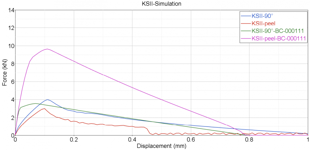
The force vs. displacement graphs when working with KSII-90° and KSII-peel simulation models is showing a significant variation in output.
Please find the graph attached, BC -000111 artificially applied to cohesive element nodes.
The observed graph with BCs are similar to my experimentation results, does that mean I need to always apply BC 000111 to cohesive elements?
Any explanation on why this is happening, could be of great help.
Regards,
Chaitanya
Master's student
Answers
-
Hi Chaitanya,
From my understanding you applied a boundary condition to cohesive element nodes, that is transalational dof were fixed. And then, the simulation data was matching with experimental data. Please correct if I'm wrong.
0 -
Hi George,
No,
translations in X,Y & Z are free
Rotations along X,Y & Z are constrained.
0 -
Hi Chaitanya,
I'll check regarding this and will update you very soon.
0 -
Hi Chaitanya,
Please share the model files (before applying BCs and after applying BCs) through the secure file transfer link available in signature, so that we will check and update.0 -
Hi,
Received your files and we are working on it. We will update you soon.
0 -
Hi George,
Any progress regarding my model ?
Regards,
Chaitanya
0 -
Hi Chaitanya,
The behavior seems to be strange as nodes of solid elements used for the cohesive layer do not have rotational DOFs. I have reported the same to the development team and waiting for their suggestions. And i'll update you the developments.
0 -
Hi George,
Did you get some update from development team?
Warm regards,
Chaitanya.
0 -
Hi Chaitanya,
This is reported and if they find any issues related to this, they will fix it up in the next update. Meanwhile we will also recheck the model.
0