How to find out problem contact among many contacts?
Hi all,
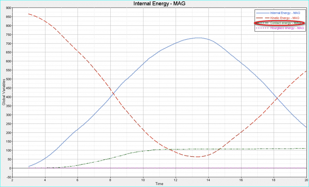
In my model, there are many contacts. From the result, I found the contact energy was large. How can I find which contact makes the large contact energy? In LS-DYNA, each contact energy can be output separately. However, in Radioss, it seems that we can only output total contact energy through global variables.
<?xml version="1.0" encoding="UTF-8"?>
Best Wishes
Roy
Answers
-
Hi Roy,
These are global curves and global results are plotted. Usually this high contact energy can be caused by friction. If you set the friction coefficient to zero and rerun and that removes the large contact energy then you can ignore the same.
You can try creating output block for the interfaces from which you can request for various output for each interface. Please go through /TH/INTER in Help Menu.
0 -
Altair Forum User said:
Hi Roy,
These are global curves and global results are plotted. Usually this high contact energy can be caused by friction. If you set the friction coefficient to zero and rerun and that removes the large contact energy then you can ignore the same.
You can try creating output block for the interfaces from which you can request for various output for each interface. Please go through /TH/INTER in Help Menu.
Hi George,
1. I don't define friction in my contacts. But the total contact energy is large.
2. Through /TH/INTER, we can only output contact force, not contact energy.
So how can I find out the problem contact which resulting the large contact energy? There are many contacts in my model.
Roy
0 -
Hi,
Contact energy is coming due to penetrations in the model. So the solver applies a force to remove penetration and this work done results into contact energy. Thus, are you having any penetrations in model , just check if any.
0 -
Hi Roy,
As Gopal mentioned contact penetrations can also result in high contact energy. Please check for the penetrations in the model.
0 -
Hi gopal and George,
The contacts are the same, but only with different drop directions (to define different rigid wall). In one case, the contact energy seems small, but in another case, the contact energy seems large. So I think the penetration is not a problem.
Roy
0 -
Hi Roy,
Can you be more clear on the contacts in the model?. Which type of contacts are there in the model?.
Ensure the recommended contact parameters are followed for interface Type 7:
Istf=4
Igap=2
Fscale_Gap=0.8
INACTI=6
Gap_min=
Fric = 0.1
Iform=2
0 -
Altair Forum User said:
Hi Roy,
Can you be more clear on the contacts in the model?. Which type of contacts are there in the model?.
Ensure the recommended contact parameters are followed for interface Type 7:
Istf=4
Igap=2
Fscale_Gap=0.8
INACTI=6
Gap_min=
Fric = 0.1
Iform=2
Hi George,
My simulation was about package dropping and I did different edge dropping simulations with different edge on the bottom. So in different edge dropping model, the contacts did not change except a new rigid wall was defined. However the contact energy was so different between this case. What may be the possible reason?
In addition, type 2 and type 7 existed in my model. The parameter shows below.
0 -
Hi Roy,
As a workaround can you set the friction to zero, Istf to 4 for Type 7 interface, run the analysis and review the contact energy.
0 -
Altair Forum User said:
Hi Roy,
As a workaround can you set the friction to zero, Istf to 4 for Type 7 interface, run the analysis and review the contact energy.
ok, I'll try it. If you have other suspection, please let me know. Thank you.
0 -
Hi George,
Do you have any suggestion on how to set different parameter values of Type 2 contact?
Thank you
Roy
0 -
-
Altair Forum User said:
Hi George,
Is there something we have to take attention when defining Type 2 contact, like how large 'Dsearch' parameter and so on?
Roy
0 -
Hi Roy,
Dsearch is the distance for searching closest master segment. I would recommend to leave this as default.
0 -
Altair Forum User said:
Hi Roy,
Dsearch is the distance for searching closest master segment. I would recommend to leave this as default.
Hi George,
Type 2 interface was defined by selecting two different nodes set as master and slave. So how does the solver connect one slave node and one master segment?
Roy
0 -
Hi Roy,
A tied contact is defined by a group of slave nodes and a master surface and the slave nodes are kinematically tied to the master surface. Warnings are displayed in the starter output file if a slave node cannot find a master segment within the search tolerance
There is also an option to define Type 2 interface with the penalty method which removes potential incompatible kinematic conditions with Spotflag = 25. A spring element is defined between the slave node and its projection. The penalty stiffness is constant, calculated as the mean nodal stiffness of master and slave side.0 -
Altair Forum User said:
Hi Roy,
A tied contact is defined by a group of slave nodes and a master surface and the slave nodes are kinematically tied to the master surface. Warnings are displayed in the starter output file if a slave node cannot find a master segment within the search tolerance
There is also an option to define Type 2 interface with the penalty method which removes potential incompatible kinematic conditions with Spotflag = 25. A spring element is defined between the slave node and its projection. The penalty stiffness is constant, calculated as the mean nodal stiffness of master and slave side.Hi George,
As you said, I think the master surface to a slave node is searched by the distance to the slave node and the closest master surface is selected. That is to say, for a slave node, only one master surface connects to it (the closest master surface I think). And for a master surface, may be many slave nodes connects to it.
I think the tied contact only works between slave nodes and its master surface. That is to say, the relative position of one slave node and its master surface stays unchanged.
1. I don't know if there is some mistake about my above understanding.
2. How to define Type 2 contact easily in HyperMesh? I suspect the tied contact if I define slave nodes with one group of nodes and master surface with another group of nodes. Maybe a wrong master surface was connected to a slave node. So how to check the only corresponding master surface by selecting one slave node randomly?
3. Could I model interference fit with type 2 contact?
Thank you
Roy
0 -
Hi Roy,
In a Type 2 interface the contact between the two surfaces is tied. No sliding or movement of the slave nodes is allowed on the master surface.I'm attaching the Theory Manual on Type 2 interface for better understanding.
Please go through https://www.youtube.com/watch?v=-HdECgBC_lM&index=2&list=PLQ7KUGFuVz4u5y3SvIEIU07427-gATaG6 which shows creating Type 2 interface in HyperMesh - RADIOSS interface.
I doubt whether interference fit is possible with Type 2 interface. There are two options for interference fit. First you can simulate the physical press fit process in RADIOSS. Define contact between the two parts, constrain one part and apply an imposed displacement on the other part and simulation the physical press fit process.
Second option is to use /INTER/TYPE24 contact and set INACTI=-1 which will apply forces to remove initial intersection caused by the press fit. The one limitation with INACTI=-1 is that it applies the force all at once and for large initial penetrations the force can be too large. To reduce the force you can use the STFAC option on /INTER/TYPE24. In the attached model, STFAC=0.25 seems to give reasonable results. Run the model with STFAC=1 (default) see the difference. I ran the attached model in RADIOSS version 2017.1 but 14.0.230 or 2017.0 should also be fine.
0