Impdisp - Rotation around local coord. system not working

Altair Forum User
Altair Forum User
Altair Employee
edited October 2020 in Community Q&A

Hi there, hope someone can help me.


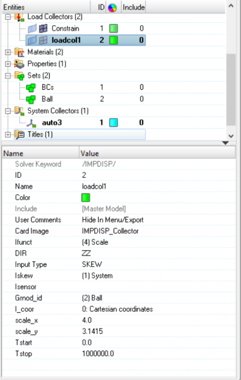
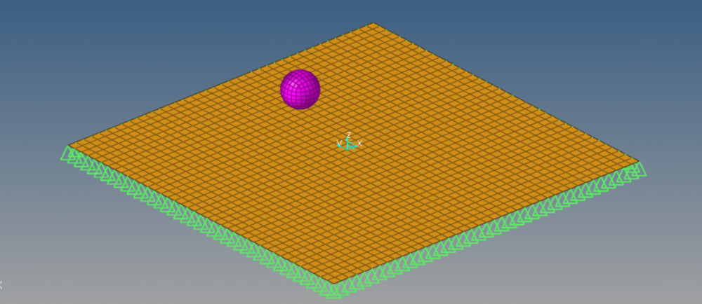
I am trying to make this ball rotate around the Z axis of the local coord. system created by me (skew in the middle of the plate). I don't know why, but the ball keep spinning around its own Z axis. I already tried creating RBody, cylindrical system, changing from /Skew to /Frame... nothing of that worked, it always rotates around its own axis. What am I doing wrong? 


<?xml version="1.0" encoding="UTF-8"?>image.thumb.png.585532d2364b4c5e50873e2822ef04b4.png
<?xml version="1.0" encoding="UTF-8"?>image.thumb.png.a17367ac716728aea4835434969ec30c.png


Thank you.

Tagged:

Answers

  • Altair Forum User
    Altair Forum User
    Altair Employee
    edited August 2018

    Hi,


    Can you add /TRANSFORM/ROT and check if this helps?


    <?xml version="1.0" encoding="UTF-8"?>TRANSFORM.png

  • Altair Forum User
    Altair Forum User
    Altair Employee
    edited August 2018

    Hello Prakash,


    Thank you for the reply. Well, I've never done /TRANSFORM/ROT before, but I went through the guidelines and tried it. Still doesn't work. Keep spinning around it's own axis. May I share my model with you? I already attached the .hm


    image.png.2918ce6c824e17f887949b316fc207c1.png

    Unable to find an attachment - read this blog

  • Andy_20955
    Andy_20955 New Altair Community Member
    edited August 2018

    Hi,

     /TRANSFORM/ROT  will rotate the initial model but that will not make the ball have an imposed movement during the simulation.


    I believe in /IMPDISP you need to set Icoor=1 and define a local /SKEW


    Now the x, y, z DIR are.

    x= radial direction (r),

    y= azimuthal angular direction ( θ )

    z= longitudinal direction (Z)


    So you need reorient your local system so that the local z direction is the axis you rotate about.  Then set DIR=Y to get rotation. 


    I have attached a sample model.


    Thanks,

    Andy


    Unable to find an attachment - read this blog

  • Altair Forum User
    Altair Forum User
    Altair Employee
    edited August 2018

    So you need reorient your local system so that the local z direction is the axis you rotate about.  Then set DIR=Y to get rotation.


    Hi Andy, thank you very much for the hint. Now it is working perfectly, its rotating around the axis I wanted.


    Only one question about the movement, should I be able to do this linking the ball elements to a rigid body and imposing the disp. to this rigid body? Because I tried so, but then the radios (x coordinate) is increasing and I am getting a spiral. I want only one lap, returning to the original position after 360°.

  • Altair Forum User
    Altair Forum User
    Altair Employee
    edited September 2018

    Hi @Andy,


    Your help was really helpful for me to understand the method, but it also showed me that will be impossible to perform my task using the console Impdisp tool. To work around this problem I am trying to generate the path I want using hypergraph and now I would like to export this coord. data (x,y,z) and use it as the /IMPDISP points. I heard its possible to do, but I don't know how to input the data in the starter deck. Please, find attached a simplified version of my path. Could you give me some hints, please?


    <?xml version="1.0" encoding="UTF-8"?>image.thumb.png.bac24ee7e7ca4a6dbbf319b21305fe57.png


    Thank you very much.

  • Andy_20955
    Andy_20955 New Altair Community Member
    edited September 2018

    Hi,

    If you can export your x, y, z data as a function of time.  Then you could define 3 /IMPDISP, one for each direction with a time versus displacement function for each direction.

    Does the ball also need to rotate while translating in the x, y, z?

    Is this for Incremental sheet forming (or ISF, also known as Single Point Forming) ?


    Thanks,

    Andy

  • Altair Forum User
    Altair Forum User
    Altair Employee
    edited September 2018

    Thank you for the reply @Andy, yes this is exactly for SPF and the tool will be rotating around its own axis while translating. As I said, this is only one of the shapes, the other shape will be a cone.


    When you say /IMPDISP, do you mean the normal one or the /IMPSDISP/FGEO? I am not sure how to input time versus displacement functions on IMPDISP. The only way I know, I define a curve (0;0) to (1;1), and then scale it as for the dimensions I need. Should I do this input using the standard console or directly in the starter deck?

  • Andy_20955
    Andy_20955 New Altair Community Member
    edited September 2018

    I was referring to /IMPDISP. 

    /IMPDISP/FGEO moves a set of nodes from a start location to an end location linearly.  Your motion doesn't sound linear so I am guessing /IMPDISP/FGEO would not work.

    My assumption is that the ball for SPF would be rigid so you could create a /RBODY of the ball mesh.  Then on the master node of the /RBODY define 3  /IMPDISP and 3 /FUNCT one for each direction (x, y, z). 

    Each /FUNCT would be a be displacement versus time.  Like this,


     /IMPDISP/1 x displacement #   Ifunct       DIR     Iskew   Isensor   Gnod_id     Frame     Icoor        224         X         0         0      2858         0         0 #            Scale_x             Scale_y              Tstart               Tstop                    1                   1                   0                   0 /IMPDISP/2 Y displacement #   Ifunct       DIR     Iskew   Isensor   Gnod_id     Frame     Icoor        225         Y         0         0      2858         0         0 #            Scale_x             Scale_y              Tstart               Tstop                    1                   1                   0                   0 /IMPDISP/1 Z displacement #   Ifunct       DIR     Iskew   Isensor   Gnod_id     Frame     Icoor        226         Z         0         0      2858         0         0 #            Scale_x             Scale_y              Tstart               Tstop                    1                   1                   0                   0 /GRNOD/NODE/2858 IMPDISP_group_2860_of_NODE       3235   /FUNCT/224 X displacment #               Time        displacement                    0                   0                                                                                1                 0.5                              2                 1.5                              3                 3.5           ..... /FUNCT/225 Y displacment #               Time        displacement                    0                   0                                                                                1                 0.5                              2                 1.5                              5                 5.5           .... /FUNCT/226 Z displacment #               Time        displacement                    0                   0                                                                                1                 0.5                              2                 1.5                            2.6                 4.5           ....                       


  • Altair Forum User
    Altair Forum User
    Altair Employee
    edited September 2018

    Thank you so much @Andy, I did in this way and its working now. I've been struggling with this for days. I was taught initially to control displacements always from the IMPDISP card, not from the function. Now it makes much more sense, its working perfectly.


    Sorry for abusing, but may be you can help me with this too. The next phase will be to calculate spring back. I know from hyperform that we can add a second step and release the clamps to see the springback behavior. How can I do this on Radioss for my SPIF? Is it possible?


    Thank you again, your help has been essential

  • Andy_20955
    Andy_20955 New Altair Community Member
    edited September 2018

    Hi,

    I am glad it is working.  There are a few different ways to do the spring back calculation in Radioss.   I would suggest running HyperForm and looking at the options in the engine files it creates and using those same commands.  There is a tutorial HF-3070: Springback Analysis. 


    It looks like they are saving a state file (*.sta) at the end of the first simulation and then creating a second analysis and include the *.sta file from the first analysis.   To create a state file see the /STATE/DT help and comments.  You can either rerun your simulation with the state file outputs included or if you still have your *.rst files created at the end of the simulation you could create a second engine file with the state outputs in it and then run the simulation for a short amount of time.


    This is how to continue a simulation with a second engine file.


    How to create a second engine file.

    If the first engine file is named runname_0001.rad.  When creating a second engine file the number is increased by 1 for the next engine file to a maximum of 9999 engine files.  So, the second engine file would be named runname_0002.rad.  To avoid a warning message, the engine file number should also match the Run Number listed in the keyword, /RUN.  
    Example: First Engine file, TensileTest_0001.rad
    /RUN/TensileTest/1
    5.0
    /TFILE
    0.005
    /ANIM/DT
    0.  0.5
    /ANIM/TENS/STRESS/MEMB
    /PRINT/-1000
    /DT/NODA/CST
    0.9 1e-6


    Example: Second Engine file TensileTest_0002.rad with changed options.
    /RUN/TensileTest/2
    10.0
    /TFILE
    0.0005
    /ANIM/DT
    0.  0.05
    /ANIM/TENS/STRESS/MEMB
    /PRINT/-10
    /DYREL
    1.00    0.002
    /DT/NODA/CST
    0.9 1e-7


  • Altair Forum User
    Altair Forum User
    Altair Employee
    edited September 2018

    Hi @Andy, thank you very much for the help and hints. I followed your steps and tried with a mass scaled model. It ran fine, but there was no significant springback, only stress dissipation. I guess because my material properties were wrong (I used false density to learn the displacement). So I decided running a new model, using all the real mechanical properties for the Johnson Cook model...

    I don`t know what is happening with this new model now, but I keep getting this weird vibrations and buckling modules. I believe the time step is small enough, and I double checked the cards, and everything seems fine. Could you give me some cues about what could be wrong?

    My doubts are:

    Am I using the right impdisp time input (seconds vs. mm) for a 'mm, s, Mg' model? 

    Are my contact setup right?

    Are the units of the material properties right?


    Please, find a animation of the problem I mentioned, a picture about my current run and the .rad files. 

    image.png.b3ae047019b48037a4d6ad8e9db714a2.png


    Again, thank you for the help. I hope I am not taking too much of your time.

    Unable to find an attachment - read this blog

  • Andy_20955
    Andy_20955 New Altair Community Member
    edited September 2018

    Hi,

    I reviewed your files and ran them a little while.  I think the motion is caused by the lack of contact and deformation of the plane.  The tool doesn't seem to be hitting the plate very much.  The contact gap between your tool and sheet is defined as a constant value of Gapmin=0.01 because Igap=1000.  Is the location of tool correct for that small of a contact gap?  I would suggest changing to Igap=1 and then the half the thickness of the tool and sheet (more like the actual physical part) will be used to calculate the contact gap between the parts.  The initial motion of the tool doesn't cause any plastic strain which seems strange to me.  Is this correct?


    For more accurate stress results set /PROP/SHELL, N=5, I_thick=1 and I_plas=1. 


    You can also make a 2nd contact where the tool is the master and the sheet is the slave.  We call this a symmetric contact and with these two contact you basically have a suface to surface contact.


    Last, I would recommend making your sheet mesh more coarse which will increase the time step of the model and reduce the run time.  This will allow you to confirm motion of the tool and contact and get approximate results in a shorter amount of time.    Then once those are correct you can go back to your original mesh.


    Thanks,

    Andy

  • Altair Forum User
    Altair Forum User
    Altair Employee
    edited October 2018

    Hello @Andy, as always your tips were really helpful and made a lot of sense. That was indeed wrong and together with some other changes solved the problem of the small vibrations. I found out that the tool was probably approaching too fast,  building up some inertia or dynamic effect. 


    Now, as it seems to never reach an end, I am facing another problem. I hope, if not asking too much, that you can help me again with your valuable hints. I am pretty confident that it is related to the material formulation. After certain level of strains, some wrinkles start to pop up on the sheet, a behavior that we didn't see in the real test.

    The model is acting as if the sheet is still too elastic, even after a great amount of plastic strain had developed. I am using all the materials properties we have here and that I found on internet (for Aluminium 2024 T3).

    I was initially trying with Johnson Cook (Law2) formulation, now I tried with Elastic Plastic Tabulated Material (Law36), also got the same results. I plotted the stress and strain over time and it seems coherent, but I can`t figure exactly what is wrong. Do you have some ideas or directions I should look for? 


    Please, find video of the wrinkling and the plot.


    Thank you very much.

    <?xml version="1.0" encoding="UTF-8"?>image.thumb.png.ea1ddb431757885748ef0b021543968e.png

    Unable to find an attachment - read this blog

  • Andy_20955
    Andy_20955 New Altair Community Member
    edited October 2018

    Hi,

    Sorry for the late reply.  I agree it seems the material could have too high of a yield stress.  Ideally you would  have a stress strain test done on the actual material used to make the part and then use that data in your simulation. 


    If you are unable to do that, then you could try using LAW2 and reducing the yield stress to see if that helps.  I also wonder if a finer mesh would change the deformation and buckling behavior of the model.


    Thanks,

    Andy

  • Altair Forum User
    Altair Forum User
    Altair Employee
    edited October 2018

    Yes @Andy, when I reduce yield stress (or increase sheet thickness) the wrinkles disappear, but only in a level that is too far from reality. I believe too that the problem can also be related to element size. The problem is that I can`t reduce it due run time, and I can`t increase it due geometry.


    Maybe you can help me on an suggestion:

    My whole simulation path, if displacement were to be imposed in seconds, is taking 591s, what with a timestep of 1e-6 will take 10 days to run (which is kind of a problem here). The problem is if I increase element to a huge size (like 15mm lenght), I can only reduce the time step to I would say 2.5e-6, then it takes 5 days. So, still doesn`t help a lot (and we loose all the precision). Another thing I am noticing, is that even when I don`t use DT/NODA, with zero mass added, I always have 99.9% error. Maybe because my simulation is too long? What can be the reason?


    Do you think its possible to imposed the displacement in milli seconds? What do you think about the dynamic effects on the Single point incremental forming? I need to find a way to run it faster.... 


    As always, thank you very much for the help. 

  • Andy_20955
    Andy_20955 New Altair Community Member
    edited November 2018

    Hi @fcolomb

    Sorry for the late reply.  Concerning run time,, you can try applying the load faster then the actual forming.  This is often still valid if the kinetic energy doesn't get too high. 


    Next, to increase the time step you could use /DT/NODA/CST and define a higher timestep which will add mass in the model.  Alternatively, you can artificially increase the density of the whole part to increase the time step.

    Last instead of using /DT/NODA/CST or increasing the density, you could try using advanced mass scaling.  /DT/AMS in the engine and /AMS in the starter.  Using AMS you can normally increase the timestep by a factor of 10 - 20 time your original timestep.  The AMS method requires more computations so your simulation will run approximately 4-10 time faster. 


    With all these methods, I would recommend running the model a short amount of time with and without these options and compare the results to make sure these options give good results.  The amount of mass add using /DT/NODA/CST or using the AMS is model dependent so you have to validate using these options.


    Last concerning the energy error. I suspect that is coming from the friction which is included in the contact energy.  If you have high contact energy relative to your total energy you can get a larger error.  Plot the contact energy and compare to the TTE: Translational total energy.  If this is true then it is OK to ignore the energy error.

    Thanks,

    Andy