SPRING2N and RBODY Connection
Dear all,
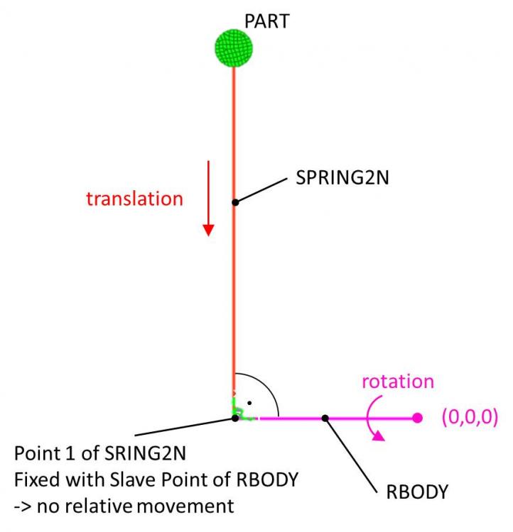
I have a problem defining the right connection between a rigid and a spring (please find a picture attached).
I want to design a simultaneous movement of a Part by rotation around global zero and translation along a spring (translational KJOINT).
My Problem is how to connect SPRING2N and RBODY to ensure no relative movement in the connection point.
Also attached is a test-model of the problem.
Thanks so much!
Best regards
Kerschten
Answers
-
Hi Kerschten,
We are working on your query and will update the progress very soon.
0 -
Hi,
I think you need to use coincident node option for connecting same node of spring to the rbody.
0 -
Hi gopal_rathore,
thanks for reply!
There are no coincident nodes in the model. Slave node of RBODY equals first node of SPRING2N. Connection between spring and rigid is working well but spring has rotational dof around slave node of RBODY which is what I have to avoid.
0 -
Hi George P,
Thanks for your files. I worked on your deck and changed the masses. Attached you find the new version. This time, the movement I want to realize nearly seems to work with few oscillation's (although I want to avoid oscillations and damping increases calculation time).
My problem is the displacement in X direction of the spring (between nodes 3 and 5). This is not intended. Original value is 100 mm before movement. After rotation displacement of the spring is around 115 mm despite the movement in x direction has to be 0 mm ('no_translation' curve).
Centrifugal force is really low and translational stiffness is really high. I don't know why there is a displacement in X direction. Doesn't make sense to me. Can you please look at the deck? Is there any other connection like a translational joint ideally having rigid behavior in every direction?
Thanks and best regards
Kerschten
0 -
Hi George P,
please have a look at the distance (magnitude) between nodes 3 and 5 in the video attached made from your 'model.h3d'. Distance is starting with 100 mm and ending with approx. 117 mm. There was no additional movement applied. Where does it come from?
0 -
-
-
Hi Kerschten,
This seems bit strange, Will check and update you.
0 -
Hi George P,
anything new on this topic?
0 -
Hi Kerschten,
This /IMPVEL loading condition is acting as a boundary condition in X direction. At every point listed in the function user is imposing 0 movement in X direction.
0 -
Hi George P,
you're right, this is like it should be. Unfortunately it is not working, since the part is moving in x direction??
0 -
Hi Kerschten,
This movement is because of rotation provided in ZZ direction. You can try imposing the same /IMPVEL condition in ZZ direction for the component and review the distance between the nodes.
0 -
Hi George P,
thanks for the suggestion! I don't know if I understood right but what I did is not working :-(
0 -
0
-
Hi George P,
in this case, spring and rigid beam do not stay rectangular to each other :-(
0