The Siemens Community Catalyst program was co-created with our community to acknowledge technology leaders who consistently contribute to the Siemens Community. Nominations are accepted on a rolling basis.
what can be the different reasons for getting 'INFEASIBLE DESIGN (AT LEAST ONE CONSTRAINT VIOLATED)' error
Unable to find an attachment - read this blog
Hi Sahil,
Looks like one of the constraints is not working with the model/problem. Can you paste the out file to check which constraint is violating?
hi Prakash,
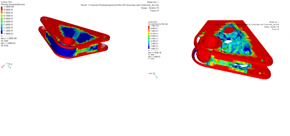
thanks for the response,i overcame that problem. the model is now feasible ,but the problem now is that the material reduction is not appropriate,PFA the model and mention any changes /improvements
What do you mean by not appropriate, can you please explain?
by appropriate i meant,it is removing material from places where by practical experience i can definitely say it shouldn't .
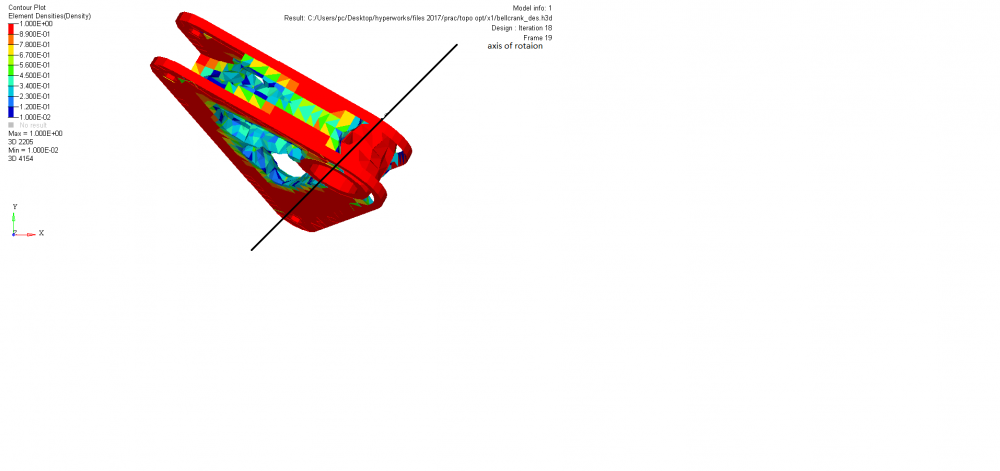
i am also doubtful about the constraints i have applied ,in this model as the axis of rotation is neither x,y nor z . so which DOF should i select in the constraints panel.
the largest hole has to be bolted,which will prevent its translation motion,but will only allow rotation about an axis (marked in image )
<?xml version="1.0" encoding="UTF-8"?>
Sahil,
What makes you think the results are wrong?
There is more material where the load is more which makes sense. Maybe you should play a little with manufacturing constraints.
in this model as the axis of rotation is neither x,y nor z . so which DOF should i select in the constraints panel.
The best way is to orient the model such that the hole axis is alligned to any of global axis.
Can you please tell the procedure, how to allign the model with respect to the global axis in hypermesh.
I guess you are using the part aligned with the car axis. If you know the angle you could go to (Tool - rotate)
Select the component (if the mesh is in the same component as geometry) and then rotate the same as the angles you get from the car system.
The easiest way, I think, is to align the part in the CAD model from the start. It's easier to play in the CAD program then in the HM.
Another thing, try first a simpler SHELL model to play with manufacturing constraints of the topology optimization and then if you see the need try with the 3D elements.
Hope it helps,
Best regards,
Gonçalo
The best way is to get the angle from CAD and rotate using ROTATE option in HyperMesh.
go to Tools Page>> Rotate>> Elements to rotate by a specific angle.
Join us for a community conversation on how High-Performance Computing (HPC) and Simcenter PSIM work together to meet the increasing demands of modern power electronics simulation. During this one-hour technical session, you'll discover how leveraging HPC can speed up simulations, improve scalability, and empower engineers…
Join us for a community conversation on accelerating your motor simulation workflow with Simcenter Simlab. In this beginner-friendly session, we'll introduce the platform's automated model-building capabilities and show how easy it is to set up your first electric motor analysis. You'll see the basic steps of geometry…
Join us for a Community Conversation where we'll discuss practical approaches to analyzing complex electromagnetic models using hybrid solver techniques. This session will provide a general overview of how different computational methods can be combined within a single simulation to address models containing varied…