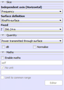
Power Transmitted Through Surface equal Total Power?
I have the following EDITFEKO code:
** Near field: NearField1
DA: 0 : 0 : : : 0 : : : 0 : : : 0
OF: 1 : 0 : : : : 0 : 0 : 0 : 0 : 0 : 0
FE: 3 : 5 : 5 : 5 : 1 : 0 : 0 : 0 : 125 : 90 : 325 ** NearField1
I displayed the information generated in cartesian coordinates (POSTFEKO) and it gave me 'Power Transmitted through surface' on a specific 'Surface Definition' and 'phi' angle and obtain a wattage that could not possibly represent a specific point. Does this mean that this is the total power that is part of an infinite surface? If I select RhoPhi surface and a specific height, is that surface infinite?
Is there a way in which I can get the specific power in a point at a specific height? Or does this depend on the antenna used for reception? I see that I can get the Electric Field values at a specific point but not power.
Thanks in advance
Answers
-
Hi Norman
In your example you requested near fields to be calculated at various points in a 3D volume with the volume being defined in the cylindrical coordinate system.
The power quantities you are displaying in POSTFEKO would be the power transmitted through a finite 2D surface - obtained by integration over the near field points sampled on that surface. Specifically in the image above you would then get the power transmitted through a Rho-Phi surface at Z=396.24m with the surface ranging from Rho=0, Phi=0 to Rho=500 (feet I assume), Phi=360 degrees - therefore a disk-shaped surface with a radius of 500 feet at a height of 1300 feet.
If you are trying to simulate the power received by a specific antenna, I would recommend that you use the Receiving antenna (RA card if you are using EDITFEKO) option. This allows you to represent a receiving antenna by importing the antenna far field pattern, near field aperture definition or spherical modes and place it at a specific location. This would then be used to determine the power that this specific antenna would receive.
Please have a look at Example B2 of the FEKO Examples Guide (ExampleGuide.pdf located in the doc folder of your FEKO installation) for more information.
Regards,
Johan H
0 -
Hello Norman,
In addition to Johan's comments, you will notice that if you have requested both electric and magnetic field values (as you have), the field request will show Electric fields, Magnetic fields, SAR and the Poynting vector. I think the Poynting vector quantity is what you are looking for. Not that this will not be listed under Power, but under Near fields (you are looking for an icon that has only a near field icon and not a near field icon with a power icon next to it).
0 -
Altair Forum User said:
Hello Norman,
In addition to Johan's comments, you will notice that if you have requested both electric and magnetic field values (as you have), the field request will show Electric fields, Magnetic fields, SAR and the Poynting vector. I think the Poynting vector quantity is what you are looking for. Not that this will not be listed under Power, but under Near fields (you are looking for an icon that has only a near field icon and not a near field icon with a power icon next to it).
Hi JIF. Thanks for your comments.
How can I convert the Electric field to the Poynting Vector? Is it something like E^2/377 ? Also, once I have that information, do I multiply it by the effective area of my receiving antenna to obtain the Power at that specific point? I just want to have something to compare to when following Johan's advice.
0 -
Hello,
See section '9.4.2 Near fields' in the documentation for the equation of the Poynting vector (calculated for E and H). You can calculate it from E or H if you know that the fields represent a traveling wave since you then know the relationship between E and H, but that is not the case for near fields in general. There are many EM text books with details regarding the Poynting vector, but wikipedia (https://en.wikipedia.org/wiki/Poynting_vector) also has some info for you.
To calculate the power flowing through the surface you need to perform an integration of power flux density multiplied by (dot product) the normal vector of the surface. Since you only have the field values at discrete points, that means that you need to associate an area and normal to each of the near field points (and your results should improve as you sample finer).
I hope that helps.
0