Contact in composites

Altair Forum User
Altair Forum User
Altair Employee
edited October 2020 in Community Q&A

Dear Sir,


I want to do a three point bending test of carbon fiber laminate in Hypermesh with Radioss.

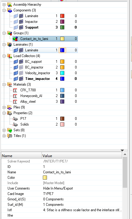
I found something puzzle when i create the contact between components after i had defined materials, properties (CFK using M25_COMPSH and property with it using P17_STACK), plies, laminate and some of boundary conditions.

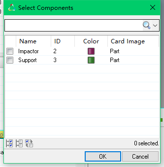
I chose TYPE 7 as the card image to let laminate be a slave entity and impactor be a mater entity but i found i cannot select my laminate component in the option(i can only see other component) 

Is there any mistake in my operation? Here are some pics under. 

I am exactly green hand in radioss, my apology... and I hope someone can help me on this. 

<?xml version="1.0" encoding="UTF-8"?>1 (2).png

<?xml version="1.0" encoding="UTF-8"?>2.png

<?xml version="1.0" encoding="UTF-8"?>3.png

Tagged:

Answers

  • gopal_rathore
    gopal_rathore Altair Community Member
    edited May 2018

    Hi,

    Please check the card image for the component 'laminate', is it set to PART? 


  • Altair Forum User
    Altair Forum User
    Altair Employee
    edited May 2018

    Hi @Dawnblade


    There is no special contact as such for composite laminate.


    Make sure you have assigned the /PART card image is assigned to LAMINATE component and check whether the elements are properly organized in the same. 


  • Altair Forum User
    Altair Forum User
    Altair Employee
    edited May 2018

    @Prakash Pagadala @gopal_rathore

    tks for ur help, i forgot to assign the /PART to component!

  • Altair Forum User
    Altair Forum User
    Altair Employee
    edited May 2018

    Hi,

    I'm new using hypermesh ad RADIOSS. 

    I need to model a laminated glass (glass-PVB-glass) and then run an impact between a rigid sphere and the laminated glass. 

    I have few questions:

    1. when I open hypermesh I need to select the user profile RADIOSS block 110 insted of OPTISTRUCT,  right?

    2. if I select RADIOSS as used profile materials an property cards are different then in optistuct: my idea is to use the M27_LAST_BRIT for glass and M34 for PVB. Is that correct?

    3. If I create laminates in optistruct I can see the in the screen (I also found tutorials explaining the process for laminates creation in optistruct), however when I use the same process (create plyes and then laminate) in RADIOSS I can't see the layers on the screen. Is there a different procedure for creating laminates in radioss or optistruct? 

    4. can you suggest me a tutorial/ video/ manual to understand how to do all this step by step? Right now I'm confused and I can't find clear explanations about composites in RADIOSS.


    Thank you very much!

    Ila

  • Altair Forum User
    Altair Forum User
    Altair Employee
    edited May 2018

    Hi @Ilaria


    1. when I open hypermesh I need to select the user profile RADIOSS block 110 insted of OPTISTRUCT,  right?


    Yes, RADIOSS block 140 is also available with 2017


    if I select RADIOSS as used profile materials an property cards are different then in optistuct: my idea is to use the M27_LAST_BRIT for glass and M34 for PVB. Is that correct?

    correct


    If I create laminates in optistruct I can see the in the screen (I also found tutorials explaining the process for laminates creation in optistruct), however when I use the same process (create plyes and then laminate) in RADIOSS I can't see the layers on the screen. Is there a different procedure for creating laminates in radioss or optistruct? 

    I think this is not supported right now, But you can use P11_SANDW to model glass-PVB-glass with N=3 which is the number of layers. 

  • Altair Forum User
    Altair Forum User
    Altair Employee
    edited May 2018

    Hi,

    I tried to run a first impact with RADIOSS, but I'm getting this error: 

    'ERROR ID :           30
    ** ERROR IN COMPOSITE SHELL DEFINITION
    DESCRIPTION :  
       -- PROPERTY ID : 0
       -- PROPERTY TITLE :    
          -- MATERIAL ID : 0
          -- MATERIAL TITLE : 0
          LAW 0 IS NOT COMPATIBLE WITH THIS PROPERTY
    SOLUTION :     
       COMPATIBILITY WITH MATERIAL LAWS 25, 27, 36, 60 AND USER LAWS' 


    Can you help me figure out how to solve the problem? I can also send you the .hm file if needed. 


    Thanks, 

    Ila

  • Altair Forum User
    Altair Forum User
    Altair Employee
    edited May 2018

    Hi,


    Can you please check the material card applied in your model?


    Looks like you have used M0_VOID (LAW0) which is not compatible with compsites.


    Please use one of the below depending on your requirement.

       COMPATIBILITY WITH MATERIAL LAWS 25, 27, 36, 60 AND USER LAWS' 

  • Altair Forum User
    Altair Forum User
    Altair Employee
    edited May 2018

    Hi, 

    the laminate component has the property P17_STACK associated. However, I specified the material inside plies (first ply is glass (M27_ELAST_BRIT), second ply is PVB (M36), third ply is again glass). Right now the material card of the component is unspecified since I don't know what kind of material I should associate to it, since  it'is made both with glass and PVB. 

    I mean, is difficult to find a unique material card for something made by layers of different materials...


    Moreover, I would like to model the glass fracture as well...Can you suggest how? Is possible to specify fracture already inside the M27_ELAST_BRIT material card or should I create a new property for failure modelling? 


    Thanks, 

    Ilaria

  • Altair Forum User
    Altair Forum User
    Altair Employee
    edited May 2018

    Hi,

    For modelling glass failure I would recommend you to create a failure card for this, which will simulate a realistic fracture modelling. You can choose /FAIL/FLD (forming limit diagram) failure card for the same. User should have the FLD curve from experimental testing.

    Check this tutorial at 

    https://altairuniversity.com/conceptual-design-of-a-3-wheeler-motorbike/conceptual-design-of-a-3-wheeler-motorbike-stone-impact-simulation/ which shows the methodology for model setup.

  • Altair Forum User
    Altair Forum User
    Altair Employee
    edited May 2018

    I mean, is difficult to find a unique material card for something made by layers of different materials...

    Hi, Glass is brittle and LAW 27 can be used for that. 


    For PVB crack, there is failure law under development and may provide much better results. But for now please try as @simulation explicite suggested. 

  • Altair Forum User
    Altair Forum User
    Altair Employee
    edited July 2018

    Thanks @simulation explicite, the video was very useful. 

    Any suggestion about where the FORMING LIMIT DIAGRAM curve comes from? 

    Actually all the forming limit diagram curves available in literature are for metals. Moreover, all the tutorial in Hypermesh explaining failure for glass suggest to use the failure incorporated in the M27 PLAS BRIT material card. 

    If there is any additional tutorial available about glass rupture please let me know. Thank you. 


    Ilaria 


  • Altair Forum User
    Altair Forum User
    Altair Employee
    edited July 2018

    Hi @Ilaria


    I will check if there is any tutorial available for Brittle failure.