Difference in stress contours in Shell and hex elements
Hello Everybody,
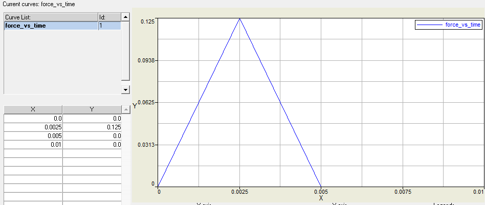
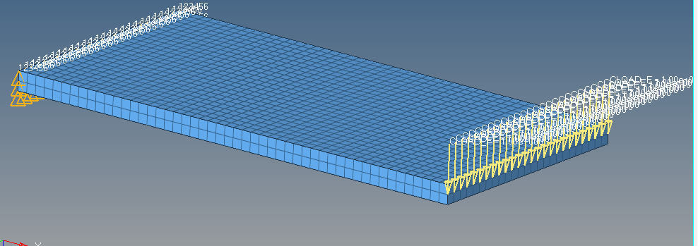
I am trying to experiment with a 4 mm thick plate (100 mm length, 50 mm width) having cantilever support at one end and a dynamic force applied at the other end. The .hm files and the force curve is attached for the reference.
I have two cases:
1) The plate meshed completely hex elements (8 noded hex)
2) The plate meshed with the shell elements (4 noded quad)
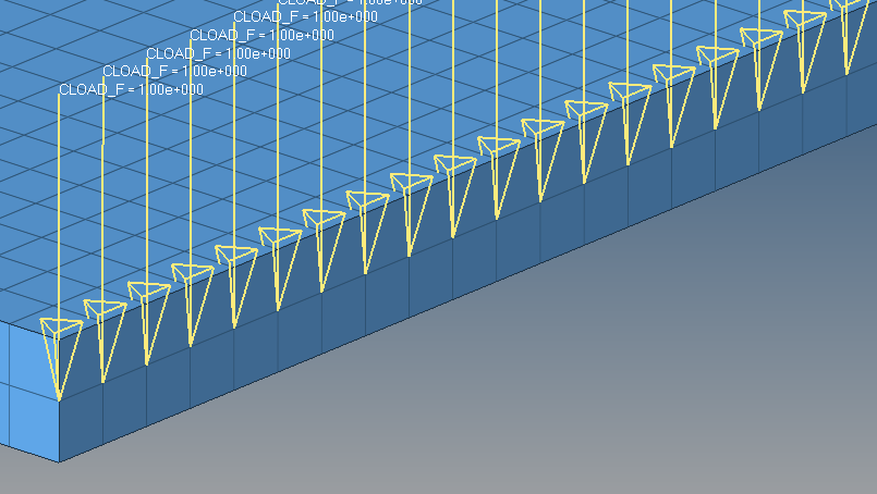
The force is applied at 26 nodes of conc. nature as shown in the figure
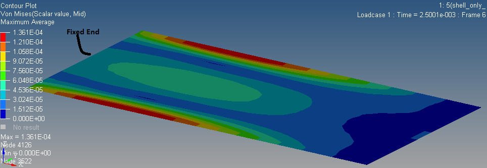
I am getting different contours in both the cases. Why am I getting so, please explain?
<?xml version="1.0" encoding="UTF-8"?>
Answers
-
How about Stress plots of Upper/Lower layers of shell model?
0 -
Altair Forum User said:
How about Stress plots of Upper/Lower layers of shell model?
how to get it ?
0 -
Hi,
Can you try the same with OptiStruct?.
Meanwhile I will check this and will update you.
0 -
0
-
In fact, it's not so simple to compare. In case of shell element, you have stress on upper/lower layers. But in case of solid element, the stress in general is not computed at surface. In my previous tests, I have to apply a very thin skin on solid element to capture the membrane stress which can be compared to shell stress.
0 -
I agree with @Q.Nguyen-Dai
0 -
what is required and which one is more correct ?
0 -
Instead, think about when to use what /emoticons/default_smile.png' srcset='/emoticons/smile@2x.png 2x' title=':)' width='20'>
0 -
i think instead of max in case of shell element if we apply average then it is more comparable.
0 -
No.
Max/Min/Average in case of shell stress will be computed between layers.
To be comparable, you have to compare solid stress of upper face to shell stress of upper layer, and so on.
0