Problem with mesh in EditFeko
Hello to everyone,
I have a meshing problem with my project in EditFeko.
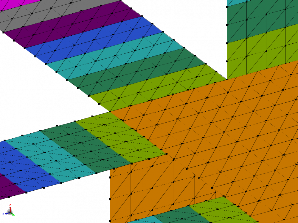
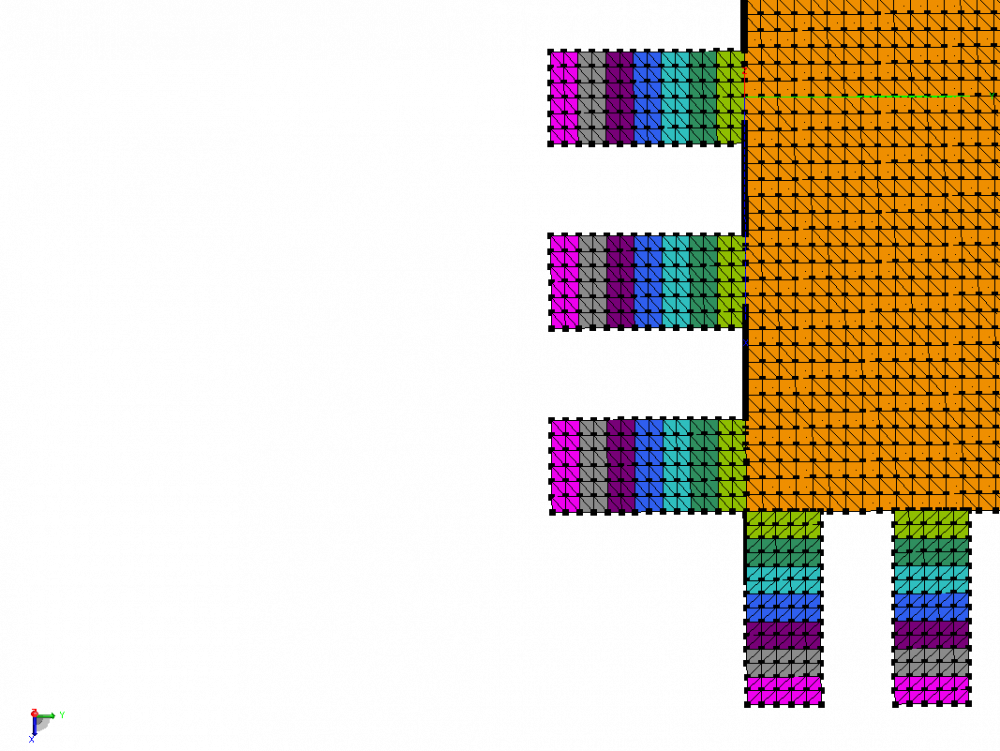
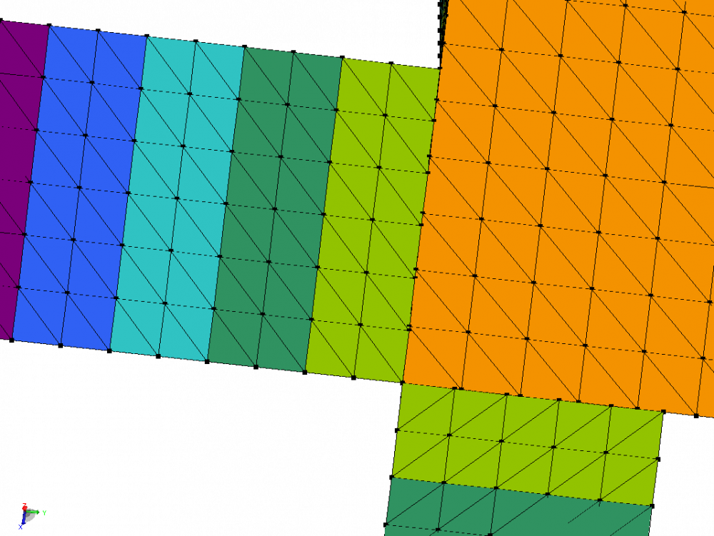
I did realize a geometry assembling various plate elements; I did set the maximum triangle edge length (with the IP card). But when I check the mesh in Postfeko (after launching Prefeko), I find out that on the common edges of the objects the mesh has been done 'indipendently' and the triangles overlaps and I can not simulate.
My question is: is there a way to 'unite' different objects in EditFeko? In this way the mesh should be done automatically on the edges.
Alternately, how can I set the mesh to let triangles on the edges of different elements match? I don't want to use a super fine mesh (that is going to make the simulation impossible)
<?xml version="1.0" encoding="UTF-8"?>
Answers
-
Hi Francesco
This can be done my ensuring that all plates have corner points (nodes) where they are connected to the corner points of other plates.
I have attached a small PRE file here that illustrates this. Two plates are created using the the PM (polygon) card. 'plate2' has an additional node at the point 'p2' which is the point where 'plate1' connects to the side of 'plate2'.
As both plates now have an edge defined between 'p1' and 'p2', (using the same mesh size) these edges will be meshed exactly the same. In EDITFEKO, using the same mesh size for two edges of equal length would always result in the same triangle edges being created along the two edges.
Regards,
Johan H
0 -
Hi
Sections '12.3.1 Meshing guidelines regarding connectivity' and '15.1.3 Meshing guidelines regarding connectivity' in the EDITFEKO chapter has some discussions on using the PREFEKO language and creating a mesh that have elements that align correctly. If you are planning on creating models in EDITFEKO, I would recommend that you read through the first few sections of the EDITFEKO chapter (sections 11, 12 and 15 in the 2017.2 manual).
0 -
Thanks Johan and JIF for your replies.
I read the manual and now I understand where is the problem with the meshing process in my project.
I know, with coding everything is achievable, but in my opinion in this way I'm going to loose all the benefits of using a 'code to create a geometry'.
In my project I use EditFeko because I create an object and then I use the TG card to copy and traslate the copies dinamically. In this way, only working on one parameter I can simply modify the whole geometry.
It seems that the method is good for simple geometries, but when you work with lots of objects (like 100 items) everytime you add a new object, you need to change the definition on the other elements connected to it (like you need to add one or more nodes).
Is it possible that there is no way to write in the code 'add a node when I align an element to another one'?
0 -
Hello Francesco S.
There is nothing easier that can be done in EDITFEKO - the faces need to be created in such a way that the edges align so that the vertices align. I have created very complicated models in EDITFEKO, but it can become quite difficult, especially if you don't know what needs to be built from the start (you are still modifying the topology of the model). EDITFEKO is powerful and support conditional and loop statements to create complex models.
Altair Forum User said:In my project I use EditFeko because I create an object and then I use the TG card to copy and traslate the copies dinamically. In this way, only working on one parameter I can simply modify the whole geometry.
In the comment above, I don't see any reason to not use CADFEKO (the preferred solution). CADFEKO supports variables allowing a user to change a variable and the entire model updates accordingly. As long as the parts are unioned, CADFEKO will take care of ensuring a connected mesh. CADFEKO also supports the Lua scripting environment allowing the model to be created in a script (probably similar to what you are doing in EDITFEKO now).
Altair Forum User said:Is it possible that there is no way to write in the code 'add a node when I align an element to another one'?
Another comment for EDITFEKO. What could be of use, if you don't rather use CADFEKO, is using the PM card to create a polygon. It should then be easy to add additional points along the edges and also to add internal points and vary the meshing lengths along the edges.
I would really suggest that you look at the CADFEKO scripting capabilities. You can even record some of the CADFEKO construction to see what the code looks like and then modify it as required to build your model script.
0