Hi all,
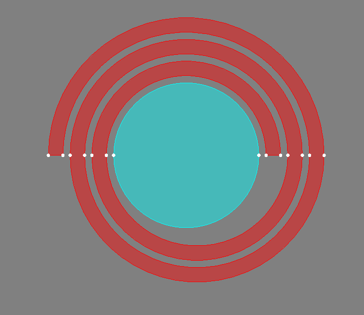
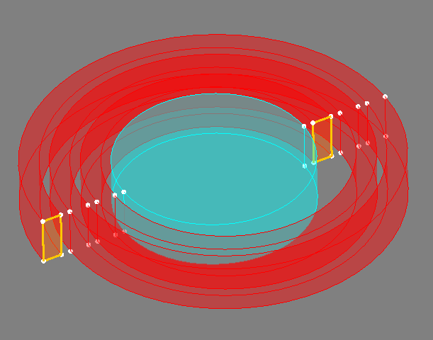
I wanted to analyze a concentric wound conductor with a ferrit core within a magneto static 3D simulation. See the screenshots below for the geometry (red is copper and turqouise is ferrit):


I tried to set the highlighted faces as the input and output terminals of a defined coil conductor. The problem is that this is not working with following error message:
KUPFER : On each volume of this region, the number of points on the
input faces must be equal to the number of points of
the output faces and to the number of lines between
the input and output faces.
Please, modify the geometry of each volume of this region
to resolve correctly this problem.
Obviously the number of points and lines is the same and also the area of the faces. I think the problem is caused by the points in between which are named parasitic points in the html-help documents.
Is there even a way to create such a geometry without these parasitic points in between?
Thanks in advance for your help.
Regards,
Felix