Multibody Static analysis fails

Altair Forum User
Altair Forum User
Altair Employee
edited October 2020 in Community Q&A

Hello,


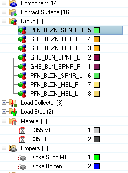
I created a shell model using 4 different parts. All of them got contact surfaces,contacts, material and property.

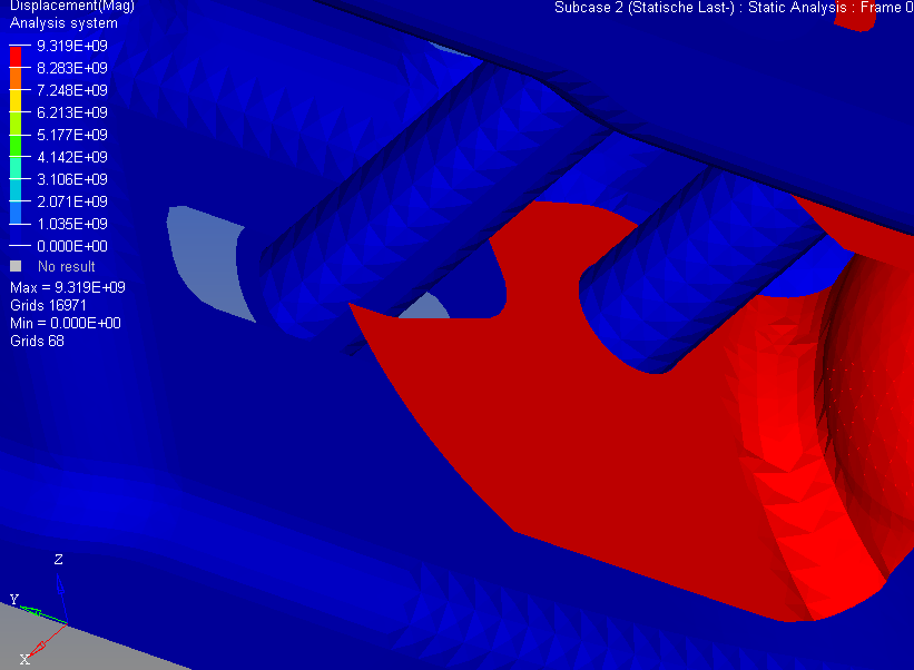
After i started the linear static analysis the parts behave as if there were no contacts between each other and penetrate.

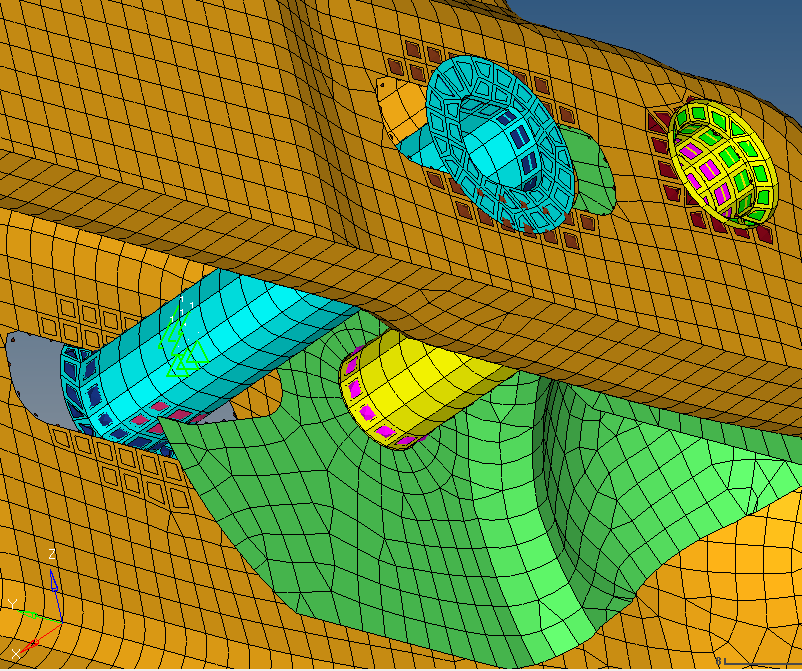
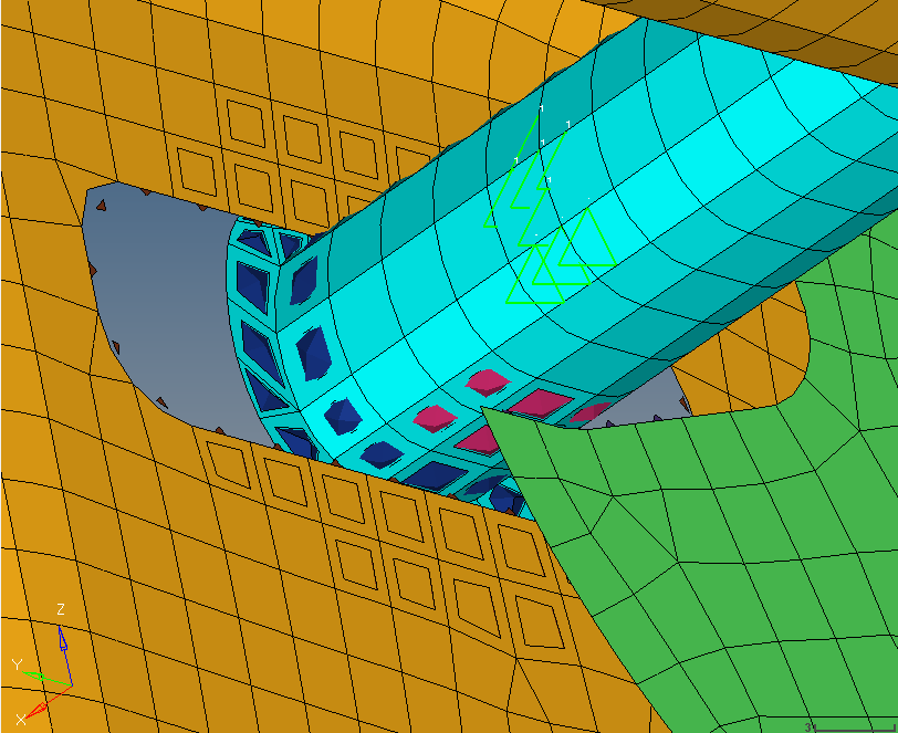
I created every single contact at the surfaces and edges which are in contact with each other. The Card Images CONTACT are all same defined:

TYPE = SLIDE

DISCRET = S2S


The Solver run is ok too, so there are no failures in the model.

Is there any step i missed to ad, or doesn`t optistruct support multi body simulations ?


Even when i start the animation in Hyperview it can be seen that the components are penetrating each other without any deformation effect.

Below i added some screenshots where it can clearly be seen that several contact surfaces have been created an added where they need to be.

I would be very thankful if somebody could tell me what to do to fix that problem, because the rest of the model and simulation is already done an has no other failure.


Greetings


Christian


<?xml version="1.0" encoding="UTF-8"?>displacements.PNG
<?xml version="1.0" encoding="UTF-8"?>props.PNG

<?xml version="1.0" encoding="UTF-8"?>screen_g.PNG

<?xml version="1.0" encoding="UTF-8"?>screen_z.PNG

Answers

  • Rahul Rajan_21763
    Rahul Rajan_21763 New Altair Community Member
    edited September 2016

    Very first thing i observe is you are running this as linear static analysis with contacts. Since contacts are involved in your case try running with nonlinear quasi static case (NLSTAT) with NLPARM card.If you have access to Optistruct online tutorials please refer below one.I see only contacts but no connectors in your FE model.

    OS-1360: NLSTAT Analysis of Gasket Materials in Contact 

    OS-1365: NLSTAT Analysis of Solid Blocks in Contact
    OS-1392: Node-to-Surface versus Surface-to-Surface Contact 

  • Altair Forum User
    Altair Forum User
    Altair Employee
    edited September 2016

    Hello Rahul,


    thanks for your fast answer.

    The NLPARM Card already helped me a lot so i could generate contact results. I followed the tutorials OS-1360, 1365 and 1392 but in none of them were any connectors and the analysis worked although. The next Problem is, that all the connectors such as Spot, Bolt, Seam or Area  are creating a fixed contact between the surfaces or edges. In my case the contacts between the parts are free, so they can move a little between each other. I thought that the contacts i already created really fit that case so that the parts can move free until they get in contact with each other.


    Is there any possibility to create a connection as i described above ?


    Greetings


    Christian

  • Altair Forum User
    Altair Forum User
    Altair Employee
    edited October 2016

    Hi Christian,

    Connectors can be used to connect nodes together, attach dissimilar meshes, distribute loads and in general provide a quick and easy way to attach things together. In your case, it seems like connectors can serve the purpose rather than defining contacts.

    Please check this link where we have covered many aspects on connectors: http://www.altairuniversity.com/modeling/meshing-2/1d-2/

  • Altair Forum User
    Altair Forum User
    Altair Employee
    edited October 2016

    Hell George, thanks for your response.


    I tried using several 1D Connectors such as bars,rigits and gaps. But non of them really fits my connection case as i need it. Here`s the explanation why all of them manipulate my results in a bad way:


    I got 2 Loadsteps in my Model, which act in a opposite direction. But as the Parts should move free within the assembly until their edges collide against each other none oft that 1D Connectors supports that behavior. One of that Loadsteps for example only afflicts one of the 4 Parts in my assembly, so that the others should get non of the stresses because the parts move away from each other. Instead because of the 1D connectors i used that one part 'pulls' the others during the simulation which should not happen and is simply is wrong. I would be very pleased if somebody could tell me how to realize such type of contact, if possible in an detailed way.


    Thanks so far for all the answers i got until now.


    Regarts Christian

  • Altair Forum User
    Altair Forum User
    Altair Employee
    edited October 2016

    Hi Christian,

    Please share the modified files ( .fem file, .out file and .h3d file) of this model to the secure file dropbox link (link available in signature).

    Please note that the files shared through the secure file dropbox link  will be confidential with us.