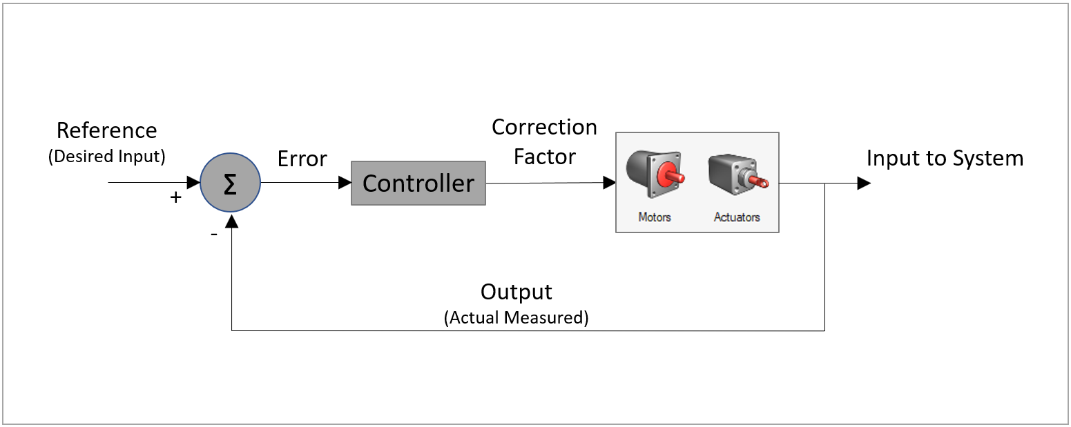
This is not meant to be a discussion on PID control theory but instead an explanation of how a PID controller, as well as a similar controller characterization called a Soft Constraint, can be utilized in Inspire Motion to represent the input response of Motors and Actuators.
The basic concept of a controller is that a desired input, such as speed, is specified for a motor or actuator. The input attempts to drive the system (or mechanism). But, depending on the counter acting loads by the system at that instant in time, the input supply may not be sufficient enough to maintain its desired speed. And so there is an actual output to the rest of the system. The difference between the desired and actual response is corrected for by varying different controller parameters. The controller outputs a correction factor with each time step that acts to increase or decreases in the input response, in order to keep maintaining the desired speed.
Basic Controller:
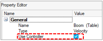
In Inspire Motion a user has the option of using a Controlled or a Non-Controlled motor or actuator, by selecting or de-selecting the “Use Controller” option in the Property Editor:
 .
.
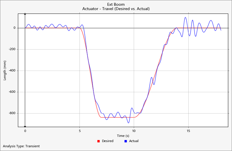
By default, motors and actuators use controllers. Control-based inputs characterize physical inputs in a more realistic sense in that, if the controller is too weak, the motor or actuator may “stall” or fail to keep up with the desired input. In a basic sense, you could say the controller is acting to represent the maximum capacity specifications of the input and, in the case of a stall, the input is not sized properly for the system. For example, in the image below, the Displacement plot shows how a PID-type controller used for the actuator is too weak for the actuator to effectively maintain the desired input timing:
Controlled vs. Non-Controlled
By default in Inspire Motion, when a displacement or speed is specified for a motor or actuator input, a controlled input is used. However, at the time of solve the math solver actually uses a force as its input, where the force is increased or decreased by the controller during the simulation in attempt to maintain the desired displacement or speed. Since this is a force-based approach, and the controller parameters (P or I or D) are fixed for the given simulation, the input can potentially be overcome by external loads and fail to supply the needed torque.
Example: A Speed motor is being used to drive a shaft at a constant speed. Based on the controller parameters used, the maximum available input drive torque might be 100 N-m. But if the load required to drive the entire system calls for 120 N-m, the motor will struggle to supply the necessary torque and the output speed plot will show “slip” or deviation between desired and actual speed. If a motor or actuator stalls completely, either the controller parameters are too weak, or there is a good chance there is a lockup in the mechanism or conflicting motions.
A non-controlled input, on the other hand, uses a constraint-type of an approach. In this case, there is no allowable violation relative to what the user specifies as an input. The input will maintain the exact displacement or speed specified, regardless of the magnitude of resistive loads acting against it. Non-controlled inputs can be useful in kinematic studies where the main objective is to understand movements, not necessarily input force or torque requirements. In the case of a non-controlled input, there is no need to be concerned with tuning controller parameters. On the other hand, avoid using non-controlled inputs when attempting to estimate required input forces or torques necessary to drive a system. Sometimes non-controlled (or “perfect”) inputs can hide other issues with the model.
Two Controller Options: PID and Soft Constraint
With a PID (conventional) controller, the user can adjust any one or combination of the three controller parameters (Proportional-Integral-Derivative) until the actual response aligns with the desired response. Once this behavior is established, one can say the controller is properly “tuned” for the given system. After this, any future deviations observed in the desired vs. actual response may be indicative of changes in the model, such as additional or unexpected loading on the system. In this case, since the input is sized with a fixed set of P, I or D parameters, the overall resulting behavior will appear as if the motor is being strained beyond its capacity.
A Soft Constraint is another (non-conventional) method for controlling motors or actuators. The concept of a Soft Constraint controller is similar in a basic sense to that of a PID in that it is providing a correction factor to the motor or actuator to correct for and sustain a desired input. Unlike a hard constraint (like a rigid Pin or cylindrical joint) which uses a Lagrange multiplier to maintain an exact and constant satisfaction of the constraint, a “soft” constraint is allowed some violation. When there is violation is detected, a penalty force is applied to counter the violation and reduce it. Finally, although a soft constraint uses P and D parameters (Proportional – Derivative), these parameters are not the same as those used for a PID controller. However, they can be thought of as accomplishing the same objective - tuning the controller response.
The following diagram shows the available controller types for motors and Actuators in Inspire Motion:

PID Controllers for MotionSolve/Activate Co-Simulation
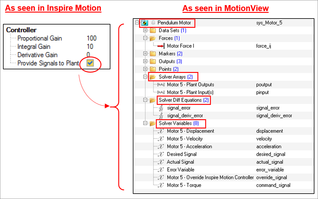
An Inspire Motion model can be quickly and easily exported to MotionView for the purpose of adding more complex controllers in the context of a co-simulation with Altair Activate (1D modeling/FMU). When models containing controlled actuator or motors are exported from Inspire Motion to MotionView, all necessary variables and arrays required for connecting the inputs to a MotionSolve plant model in Activate are automatically generated and placed into a MotionView “System”.
So, using the PID controller option in Inspire Motion can help save time in setting up the controller(s) for purposes of co-simulation. This would otherwise have to be done manually in MotionView. Additionally, the PID controllers carried over from Inspire Motion can be easily replaced with more complex controllers once the MotionView model is connected with Activate.
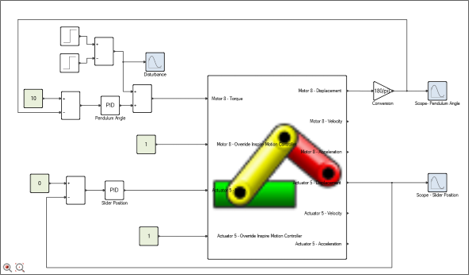
Example Altair Activate block diagram (Co-simulation model):
Additional notes:
- By default, motors and actuators use a controller (either PID or soft constraint). This is the recommended setting. If the objective of the simulation is to understand the basic motion of the system, without a focus on required force or torque to drive the system, it is recommended that a controller always be used.
- If a controller is too weak initially, try increasing the control parameters (primarily the P parameter) by ½ to 1 order of magnitude each time. Create a plot of “Desired vs. Actual” for the displacement or speed to help monitor convergence progress.
