Best Of
/H3D/NODA/GPS と /H3D/SOLID/TENS/STRESS/CORNER_DATA の違い、メリット・デメリット
始めに
テトラ2次要素の、節点位置での応力の H3D 出力要求には
- /H3D/NODA/GPS
- /H3D/SOLID/TENS/STRESS/CORNER_DATA
の 2個があります。本記事ではこれらの違いや、メリット・デメリットについて説明します。
違い
まず、どのような要素でも応力計算自体は、積分点と言われる点で行われます。これは節点の位置にはありません。しかしそれだと何かと不便なので、Radioss などのソルバーが節点の位置での応力を推測して出力し、ユーザー側で、その値を見ることができるようになっています。
/H3D/NODA/GPS の場合、Radioss が要素ごとの節点位置での応力を推測した後、通常 1節点に複数のテトラ2次要素がつながっているので、それらの要素の節点位置での応力値を平均を出して、その値を H3D ファイルに書き込みます。値を持っているのは節点です。
https://help.altair.com/hwsolvers/rad/topics/solvers/rad/h3d_noda_engine_r.htm
/H3D/SOLID/TENS/STRESS/CORNER_DATA は、Radioss は要素ごとの節点位置での応力を推測し、それをそのまま、H3D ファイルに書き込みます。値を持っているのは要素です。
https://help.altair.com/hwsolvers/rad/topics/solvers/rad/h3d_solid_engine_r.htm
このような違いがあるため、/H3D/NODA/GPS は一つの節点に一つの値を持ちますが、/H3D/SOLID/TENS/STRESS/CORNER_DATA は一つの節点の場所に、そこにつながっている要素の分だけ値を持ちます。言葉では説明が難しいので、次の図を見てもらうのが早いです。

(クリックで拡大)
素の表示では、両者は大きく違いますが、HyperView でも節点位置での平均化ができるので、/H3D/SOLID/TENS/STRESS/CORNER_DATA 側を同じような表示にすることはできます。

(クリックで拡大)
この画像に使っている Radioss モデルのダウンロード:
/H3D/NODA/GPS のメリット、デメリット
メリット:
- 節点の値となっているため、ファイルサイズを節約できます。
デメリット:
- 元の要素の値が削られているため、元の要素の値を知るすべがありません。
- Radioss 側で平均化処理済みの節点値となっているため、HyperView の他の平均化処理を適用することができません。
/H3D/SOLID/TENS/STRESS/CORNER_DATA
メリット:
- 元の要素の値をそのまま評価できます。
- Radioss 側の平均化処理がしっくりこない場合に、HyperView が持つ複数の平均化処理を比較して、しっくりくる平均化手法を探してみることができます。
デメリット:
- 全ての要素の値を残すので、ファイルサイズが大きくなります。
まとめ
メリットとデメリットを勘案して、都合の良い方を選択してみてください。

How to Perform Squeak and Rattle Assessment using Altair SimSolid
Squeaks and rattles are unwanted noises that are directly related to the perceived quality of a product. In this video, you will see how to identify and eliminate such issues using a simulation-driven approach with Altair SimSolid.
CAD geometry, loads and solved model can be found attached to this article.
Conclusions:

Extra Content About Altair SimSolid:
- Webinars, Customer Cases and more
Re: Bistatic RCS in WinProp
Hi,
Indeed, currently only monostatic RCS can be used in WinProp. This is due the fact that this feature was introduced for virtual-drive test computation acceleration were only the monostatic direction is of interest. In these cases vehicle models with a very large number of polygons can be replaced by their RCS during SRT computations, instead of being considered one by one if the full model is used.
If you only have an *.ffe with bistatic information and for some reason you cannot run/create a monostatic *.ffe, a workaround is to preprocess the file you haveand extract the monostsatic data into a new file. You can then use this file in WinProp.
There might be updates to this feature in futur releases.
Best Regards,
Zeina
 Zeina
Zeina
Auto Create Rigids
Overview
Automatically create rigidlink (RBE2) elements between nodes associated to selected surfaces (dependent nodes) and a selection of nodes (independent nodes).
Usage/Installation Instructions
From the menu bar, select File >> Run >> Tcl/tk script.
Functionality
Meshing
Subfunctionality
1D Meshing
Interface
No Specific Interface, Abaqus, Acis, Ansys, Catia, CFD, Crash, Dxf, HMascii, HyperStudy, Ideas, Iges, JT, LS-Dyna, Madymo, Manufacturing, Marc, Nastran, NVH, OptiStruct, Other, Pamcrash, Parasolid, Patran, Pdgs, Permas, ProE, RADIOSS (Block), RADIOSS (Bulk Data), Samcef, SolidWorks, Step, STL, Tribon, UG, Vdafs
Chayan
Re: OptiStruct Error #2866
Hi Fabian,
I attached a small video debugging the model, I think it is easier to understand. The model is also attached.
Let me know if you have any other query.
Thanks,
Fabian
How to continue run with Inspire Cast?
Hi everyone,
How to continue running when crashing the software?
Thanks.
Re: HyperMesh Subsystem Modeling Exercise Help
Hello Mandy,
Please find below quick feedback regarding your questions.
Question 1: the main purpose of part config is to represent all the configurations in one hm database and activate only the interested one. For instance, different design of a same part.
Question 2: the main Model Subsystem is indeed mandatory. The first subsystem in your model will always be the "Model" subsystem. This is the subsystem connected to the "Main Include".
Question 3: subsystem set is just a group of subsystem, for organization/selection purpose. For this usecase, indeed, it is optional.
Question 4: it all depends of the organize settings (RMB in the subsystem browser > Organize settings). As you'll see, you can determine which dependent entities to move when managing subsystem content and behavior if entities are shared across subsystems. For instance, a prop assign to a comp will be move by default with the comp.
Question 5: All entities moved into a Subsystem will be moved to an Include. The Subsystem always has one linked include and contents of the include and subsystem will always be in sync. Therefore, you must organize your subsystem/entities based on the include type => bulk data, subcase section or I/O section. For instance, loadsteps should be defined in a "subcase section" include type.
Question 6: not sure to understand this question... since v2023, you can create and manage instance of subsystem. Please take a look at this video => 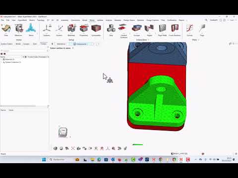 https://youtu.be/KvZuZJ7C8lw?si=u2khQjAPLVfMcGED
Question 7: yes absolutely. You can still use the entity state browser, but the active state of parts/subsystems should do the job.
Question 8: Please take a look at this tutorial from the online help and this playlist from our Altair How To Youtube channel:
https://help.altair.com/hwdesktop/hwx/topics/tutorials/hwx/model_build_t.htm
Regards,
Fred.
Re: Is it possible to split quad elements and keep the applied pressure (PLOAD cards).
Hi,
Since version 2021, there is a new option called "Automatically update sets to mesh changes", allowing to update sets of nodes and/or elements in case of re-meshing. Thus, if a pressure (or any load/contact surface...) is defined on element set, then pressure will be automatically mapped on the new set in case of remeshing.
This is one advantage of the new load management => to define loads and boundary conditions as distributed loads on sets. More details here: https://help.altair.com/hwdesktop/hwx/topics/pre_processing/entities/loads_r.htm
This solution is highlighted in the attached video.
For a model with classic loads (as in your screenshot), you must process in two steps: first create a field to store the initial pressure loads and then realize the field to map the pressure value on the new mesh.
Regards,
Fred.
Computing contact area and averaged contact pressure for RADIOSS results
Overview
For type7, type11 and type19 results, RADIOSS exports contact forces and contact pressures as nodal results.
As we collected several requests to compute contact are and average contact pressure from these outputs, we set up a report template/flexible report which computes contact area per node (contact force/contact pressure), and we added two extra contours:
- contact area per part (using result above + BCNodeTPart operator)
- average contact pressure per part (using also BCNodetoPart operator).
Usage/Installation Instructions
Access these results by loading your flexible report inside HyperView, then updating your result file (either h3d or RADIOSS animation file).

HyperStudy 2023.0 Release Highlights: New Features and Enhancements
Here are the exciting new features and enhancements in HyperStudy 2023.0.
1. Existing Data Model
A new model type has been introduced to process output files of existing data in a chosen directory. All the files containing historical data are automatically distributed to their respective run directories.

2. Measures in HyperView Connection
HyperView connection now supports Measure type entities as responses.

3. Auto-Regression for Vector Data
FAST is now available for vector fits.
4. Solver Environments
Environment variables can now be independently set or unset for each solver process.

omet