Best Of
Add and Remove Constraints During Calculation
In Altair Radioss, it is possible to define multiple engine files (e.g. _0001.rad, _0002.rad,…). This capability is a powerful feature, and some common applications include:
- Pre-tension or initializing gravity before a simulation.
- Changing the time step control options used.
- Turning on and off rigid bodies.
- Changing the write frequency of output files, such as animation (/ANIM/DT, /H3D/DT) and time history (/TFILE).
- Add or remove boundary conditions.
How to remove a boundary condition during calculation
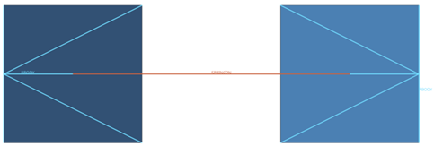
We will use a simple model with two shell elements connected by a spring element to show how to add and remove a boundary condition during calculation.
To remove the BCS during calculation, we should use multiple engine files and an engine keyword called /BCSR. These are the BCSR cards available:
- BCSR/TRA – Given node numbers will be released in specified directions X, Y, or Z for material translational DOF.
- BCSR/ROT – Given node numbers will be released in specified directions X, Y, or Z for rotational DOF.
- BCSR/LAG – Given node numbers will no longer be Lagrangian in specified directions X, Y, or Z.
- BCSR/ALE – Given node numbers will be released in specified directions X, Y, or Z for grid DOF.
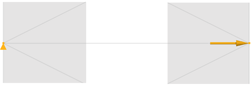
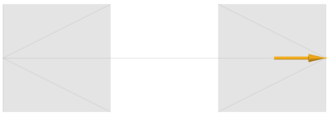
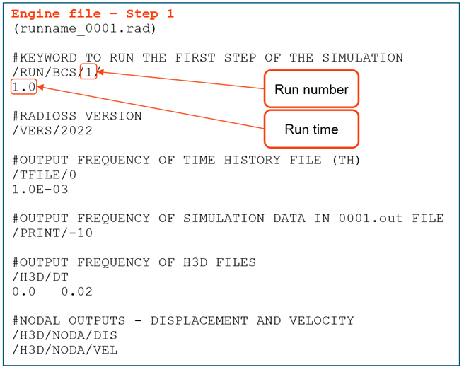
The simulation is going to be divided into two steps. In the first step, an initial velocity will be applied to the right element while the left element is constrained.
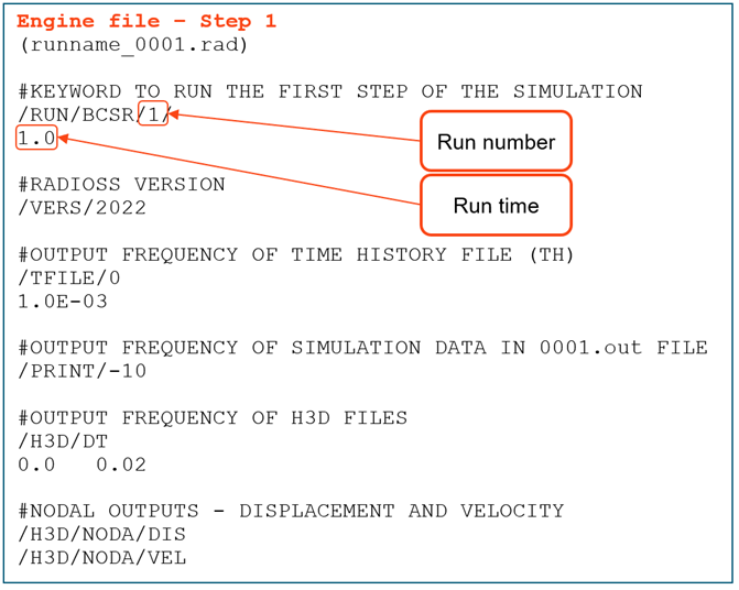
Engine file for the first step:
First step animation:
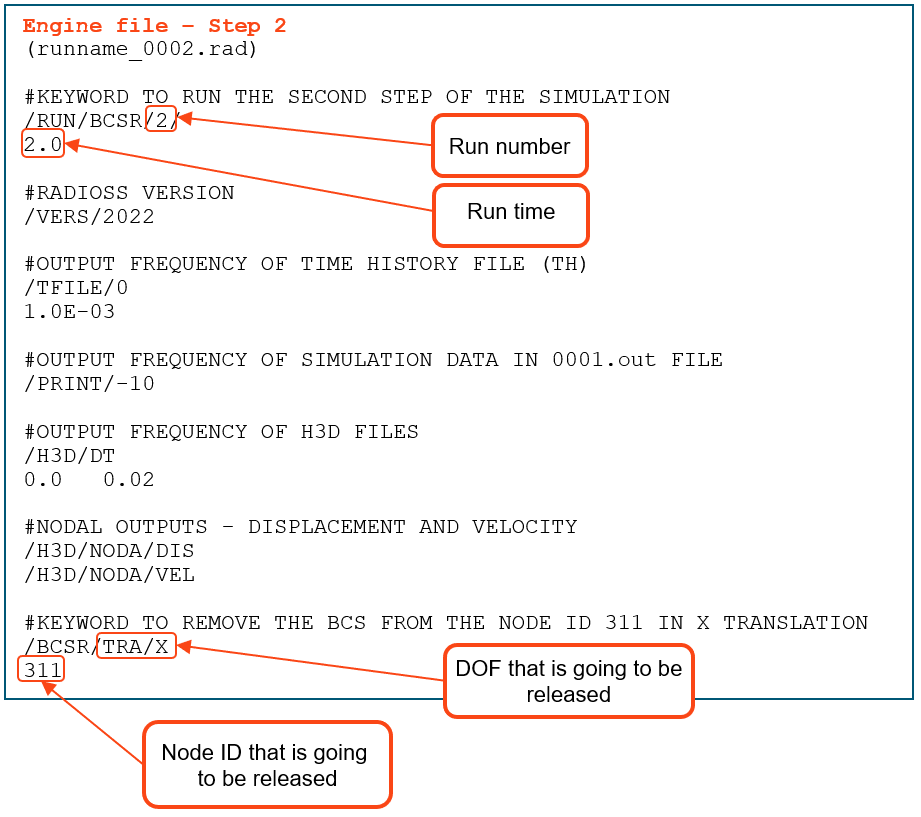
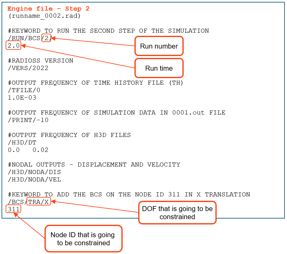
After the results from the first step, we will create the second step of the simulation. To do this, we are going to create the second engine file with the following changes:
- Copy and paste all keywords from the first engine file (in this step, if you want, you can also change the animation frequency, time step control, or turn a rigid body on and off).
- Rename it to runname_0002.rad.
- Change the run number to 2 on the /RUN keyword.
- Increase the run time to 2 (specific for this model).
- Add the /BCSR keyword, as shown in the image below.
Full simulation animation:
As you can see, when the simulation changes from step 1 to step 2, the BCS of the left element is released, and it starts moving due to the spring force.
The model can be downloaded here: BCSR_Model
How to add a constraint during simulation
To show how to add a constraint during the simulation, we will use the same model as before, but this time we will remove the constraint on the left element during the first step.
To add the BCS during calculation, we should use multiple engine files and an engine keyword called /BCS. These are the BCS cards available:
- BCS/TRA – Given node numbers will be constrained in specified directions X, Y, or Z for material translational DOF.
- BCS/ROT – Given node numbers will be constrained in specified directions X, Y, or Z for rotational DOF.
- BCS/LAG – Given node numbers will be Lagrangian in specified directions X, Y, or Z.
- BCS/ALE – Given node numbers will be constrained in specified directions X, Y, or Z for grid DOF.
Multiple engine files are used to split the simulation into two steps. In the first step, an initial velocity is applied to the right element while the left element is free. In the second step, the left element is constrained.
Engine file for the first step:
Animation for the first step:
After the result from the first step, we will create the second step of the simulation. To do this, we are going to create the second engine file with the following changes:
- Copy and paste all keywords from the first engine file (in this step, if you want, you can also change the animation frequency, time step control, or turn a rigid body on and off).
- Rename it to runname_0002.rad.
- Change the run number to 2 on the /RUN keyword.
- Increase the run time to 2 (specific for this model).
- Add the /BCS keyword as shown in the image below.
Full simulation animation:
As you can see, when the simulation changes from step 1 to step 2, the left element stops moving due to the /BCS added.
The model can be downloaded here: BCS_Model
More information about the engine keywords BCS and BCSR can be found here: Documentation BCS and BCSR
This article was originally created by Nobuyuki Fukuoka, and the Japanese version can be found here
convert collection to a single table (ExampleSet)
I need to have a table with all.
my out is
collection
table value 23:
USER_ID ITEM_ID
1 23
table value 54:
USER_ID ITEM_ID
1 54
...
I need this
ExampleSet
USER_ID ITEM_ID
1 23
1 54
... ...
Thanks
Re: Unable to execute EDEMpy file in HyperStudy
Hi Gary,
Are you using the latest version of the calibration scripts? They can be found here: https://community.altair.com/community/en/edem-calibration-kits?id=kb_article&sysparm_article=KB0121756
If the problem still persists, could you try adding the following two lines:
import matplotlib
matplotlib.use('TkAgg')
before the line
from matplotlib import pyplot as plt
Best regards,
Renan
Re: Error ID 79 : ** ERROR : DUPLICATE ID
Hi Ram,
A rigid body is defined by a set of slave nodes and a master node and the best practice is to create a master node that is not attached to anything. The master node of the rigid body should be free. Only loads and boundary conditions should be applied on the master node.
And also it is not possible to have two rigid elements connected to a single dependent node, which will create dependency issue.In Check Elements (F10) panel user can check rigid elements for conditions causing double dependency and can clear them.
Re: Error ID 79 : ** ERROR : DUPLICATE ID
HI Ram,
Please check the rigid bodies in the model. The same master node of rigid bodies is shared by a least two rigid bodies, which is an incompatible condition.
Moreover,a node of the mesh is selected as the master node of a rigid body, which is not recommended.
Please check the output block created in the model. No TH variable is defined in the model.
Re: Error ID 79 : ** ERROR : DUPLICATE ID
Hi,
Could you share us complete input deck?
Make sure that you are not having duplicate elements or empty property collectors.
Regards
Rahul R
Re: Altair Inspire® Challenge #1: Bridge Concept Design
Here's what i got.
Very nicely done, as always! Thanks for your submission!
Re: Altair Inspire® Challenge #6: Lilly Pad Optimization
Hi Mathew & everyone, i found this tricky, the optimization solution does leaves a huge gap between the outer ring (partition) and the design space. Please advice
Re: Simlation error
Hi Pravin Kumar,
the issue could be with the modelling method. Please check the following:
- furnish mass, inertia values and be correct if you are performing dynamic simulation
- if you are using contacts in your model check contact properties. it is recommended to manually mesh the geometry with a fine mesh where the bodies come in contact
- play with solver parameters like h_max, DAE, etc.. also try changing the integrator type to VSTIFF if there are flex bodies.
please let us know if any of the above helped you.
