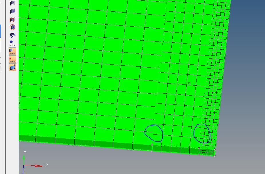
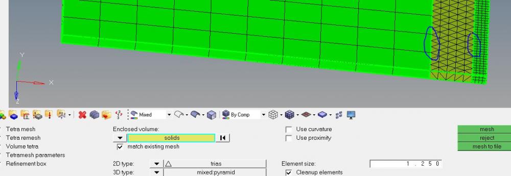
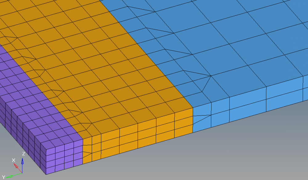
I have 3 rectangular solids of dimensions 250*52*1.5 ,250*6*1.5 and 250*2*1.5 mm respectively. I need a refinement of 2.5,1.25 and .5 respectively. But when I am using solid map option for meshing solids, though I am getting the refinement as needed, nodes of meshes at the shared edges are not getting connected as shown in the figure attached. so how can i give transition edges at the shared boundaries so that nodes are connected properly. ?? Thanks
<?xml version="1.0" encoding="UTF-8"?>