Hi all,
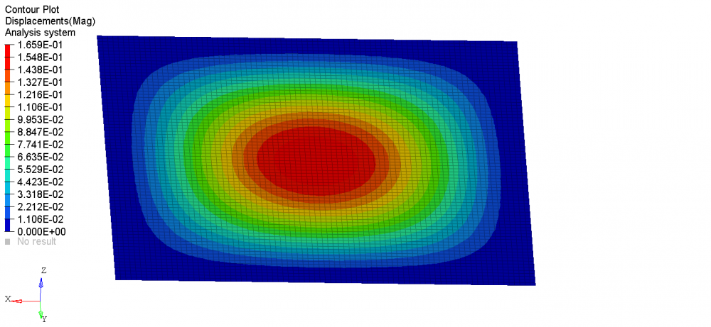
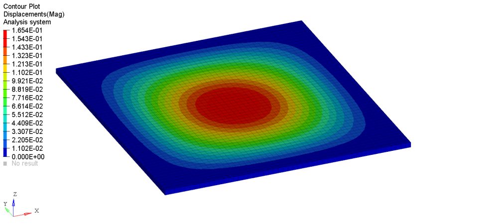
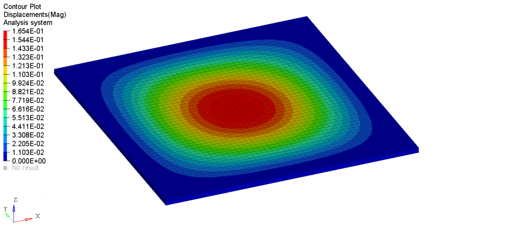
I want to compare the result of shell and solid element for a thin plate bending analysis. So I select a thin plate with dimension 100*100*2mm, the four edge of the plate are all clamped, and a uniform pressure is applied on the top surface.
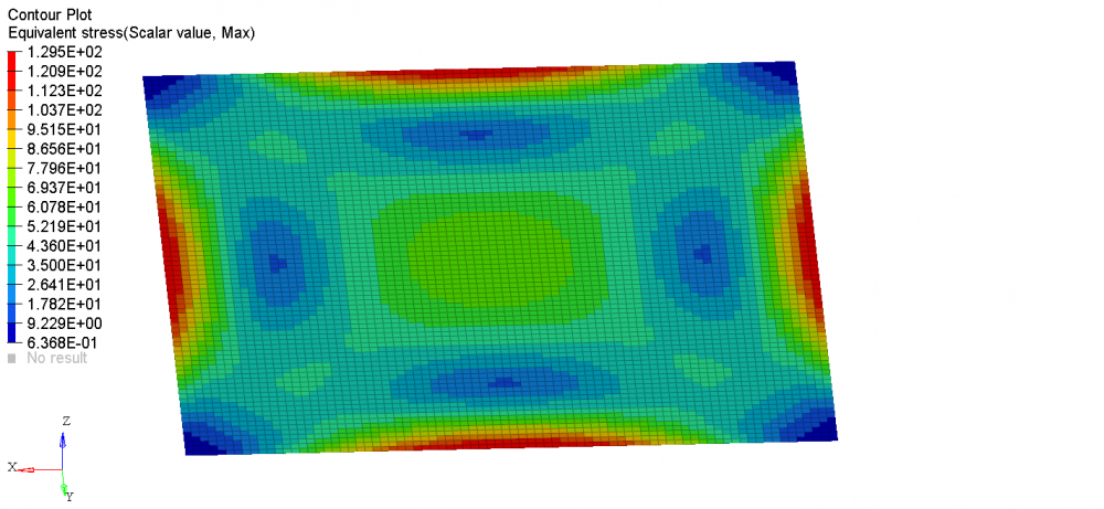
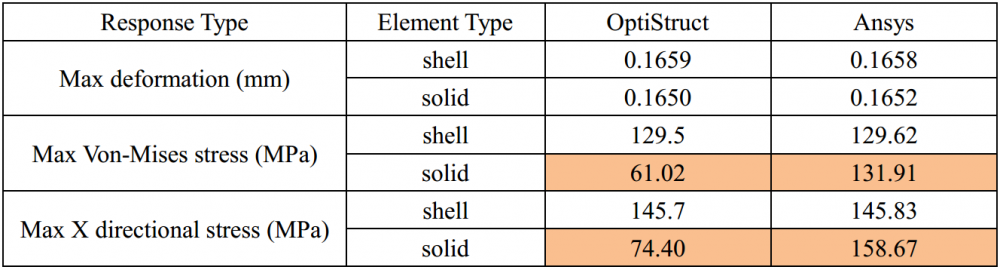
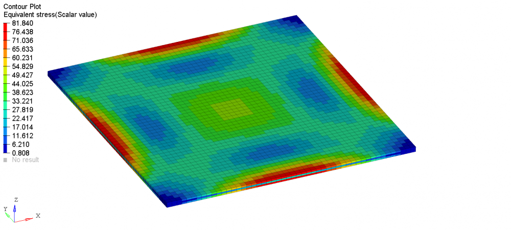
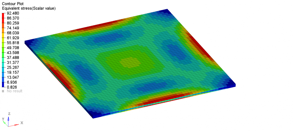
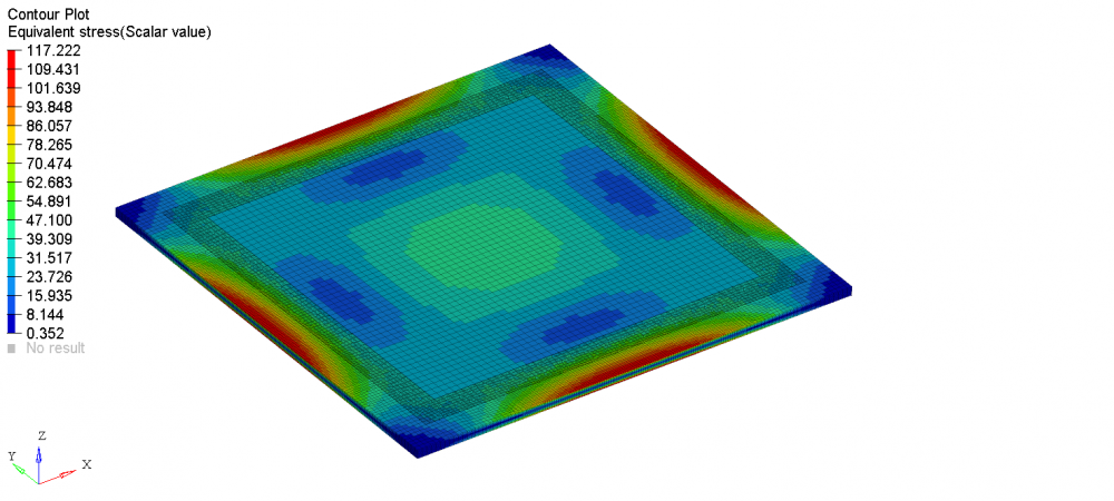
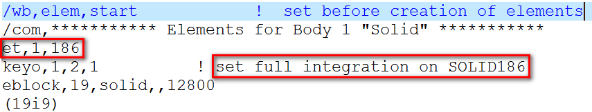
However, I got a different result from OptiStruct and Ansys with the same solid model. Both the material and the mesh are the same. The in-plane element size is 1.25*1.25mm, and there are two elements through its thickness. The maximum stress in X direction from OptiStruct and Ansys is 74.4MPa and 158.7MPa. It's so different. What's more, according to the theory, the maximum stress may be 154MPa, which makes me suspect the optistruct result.
<?xml version="1.0" encoding="UTF-8"?>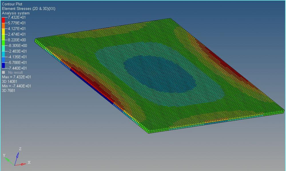 <?xml version="1.0" encoding="UTF-8"?>
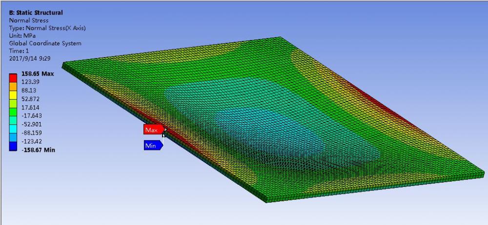
The maximum stress theory for four clamped thin plate under uniform pressure loading is given in following link
http://www.roymech.co.uk/Useful_Tables/Mechanics/Plates.html
What's the reason for this strange result? I have attached my HM file.
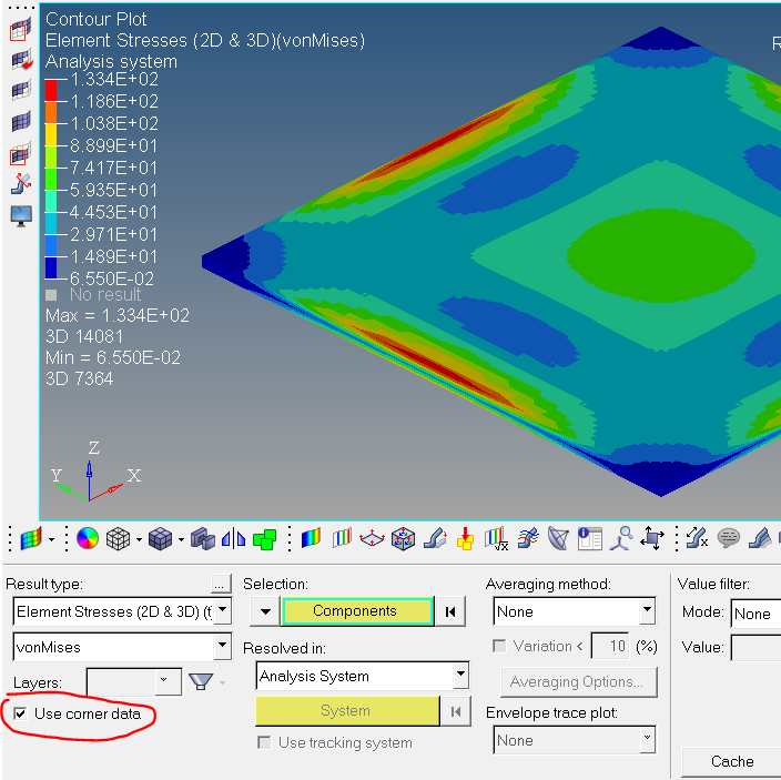
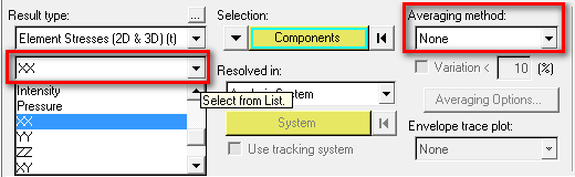
In addition, is there any document which explain the different options meaning of stress result type and average method? See figure below
Thank you
Roy
Unable to find an attachment - read this blog