AFPM running in .FeMT
Hi.
I am trying to run an axial flux motor in the e-machine extension to achieve a torque curve and efficiency map.
I have created a motor and followed the required steps in Flux. All apart from meshing the infinity box as my motor section is parallel to the y-axis and the infinity box is parallel to the x-axis resulting in the motor passing outside the box, shown in the figure below.
I have tried to perform a transformation on the Motor to move it onto the x-axis, but cannot remove the original volumes as they overlap and have tried to perform a transformation on the infinity box too, but again can't remove the original lines.
<?xml version="1.0" encoding="UTF-8"?>
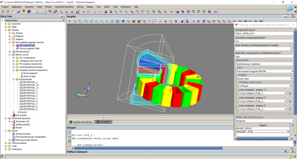
Is there a way to mesh the infinity box even with the rotor and stator passing through it? and eventually successfully run it in FeMT.
I can send the file as well if that would help.
Apologies if this is a simple issue.
Many Thanks
Find more posts tagged with
-
The electrical circuit, you don’t need to use the inductance in the case you represent the end winding. Also, I delete the inductance that you put in parallel with a current source. I put a resistance instead with a hug value.
-
About the lamination in the stator and rotor. I change also the direction. I put “1” in z axis, this allows to select he lamination direction.
-
Same error in the magnet. You put solid conductor region and you need to put a resistivity in the material.
Hi,
I checked the model that you send me. The problem come from the coordinate system that you use when you import the device in Flux modeler. You need to create a new coordinate system with shift angle (-30degree) in the z axis (see the attached project).
Other problem that I meet in your project, when I do check geometry, Flux display an error message (the geometry is not correct). When I check, I found that there is a small air gap between some volumes (between the volumes 7,5 and 3, between the volumes 6.4 and 1).
Can you correct the geometry and import it again in the modeler.
Best regards.
Hi.
Apologies for not fixing the geometry, I thought I saw geometry okay.
I have fixed all the issues as stated. But still struggling to get results in FeMT,
Attached is the fixed model
Best Regards
Many Thanks
This is a different design. In the previous thread i was simply trying to see if i could get a curve out of FeMT with any model, and thus used the example model.
This is the project I aim to get a torque curve for and hopefully understand how to reliably run models in FeMT to get torque curves.
Best Regards
Hi,
I checked the project that you send me. I found there are some errors in:
In the end when I do check physics, I get an error message:
The sliding surface of the mechanical set ROTOR
is not a revolution surface
Concerned face(s): 2 4 8 10 14 16 20 22
The error message means, that you need to separate the moving and fixed part with an air. Can you change the geometry (see the Flux 3D supervisor example, how to create the sliding surface).
Can you make this change on your geometry and solve again the project with FeMT. Before solving try do check physics to be sure that all things are correct.
Keep me informed of this solve the problem. Other thing before solving using FeMT, be sure that you have enough memory on your computer.
Best regards.
Apologies for the above reply.
I have now been able to get the model into FeMT
But every time it is failing instantly. I have run the model in FeMT from multiple directories with 1GB + free.
The FeMT file is attached
Hi,
Sorry for my latte answer. You will find attached the Flux project.
About the FeMT project, I don’t manage to solve the problem. I will send your project to our R&D team to check.
I will keep you informed.
Best regards.
Hello, is there any tutorial that you could share for designing the axial flux motor with the inner stator? As far as I see there is no example that is initially built in Flux.
Best regards,
Hi,
I understand that Stator is in center and rotor is at top& bottom. This is configuration? What is the slot-pole combination you are trying to model in Flux.
We do have a macro for this type of configuration.
Thanks and regards
Karun Teja
Hi,
I understand that Stator is in center and rotor is at top& bottom. This is configuration? What is the slot-pole combination you are trying to model in Flux.
We do have a macro for this type of configuration.
Thanks and regards
Karun Teja
Yes, the stator is in between two rotors. There will be 16 poles and 18 slots. I could see macro only for a rotor in between the stators, which is inside-out of mine. Could you help with the path for the macro for the model that I want to model?
Hi,
The 16-pole and 18-slot combination is not supported with this macro at the moment. If the slot-pole combination is 3:2 then you use the macro "Create3DAxialFluxMachine.PFM". It will be in Flux installation itself where all the macros are present.
Thanks and regards
Karun Teja
Hi,
The 16-pole and 18-slot combination is not supported with this macro at the moment. If the slot-pole combination is 3:2 then you use the macro "Create3DAxialFluxMachine.PFM". It will be in Flux installation itself where all the macros are present.
Thanks and regards
Karun Teja
Thank you for the help!
Hi,
Can you share your Flux project?
Best regards.