Hi experts :
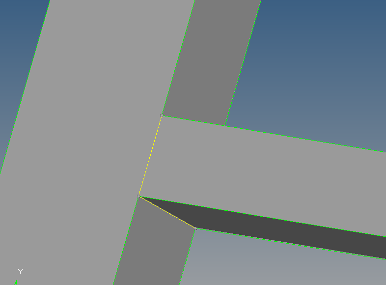
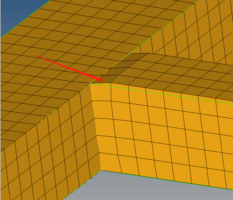
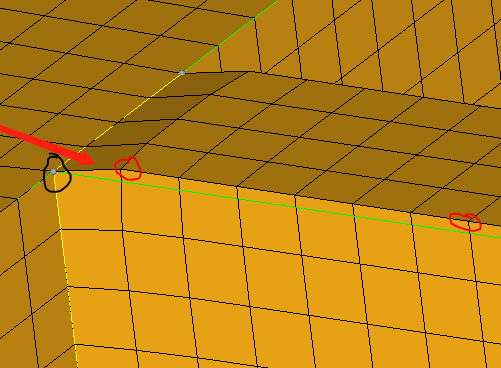
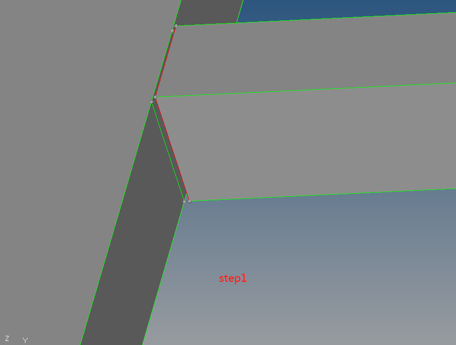
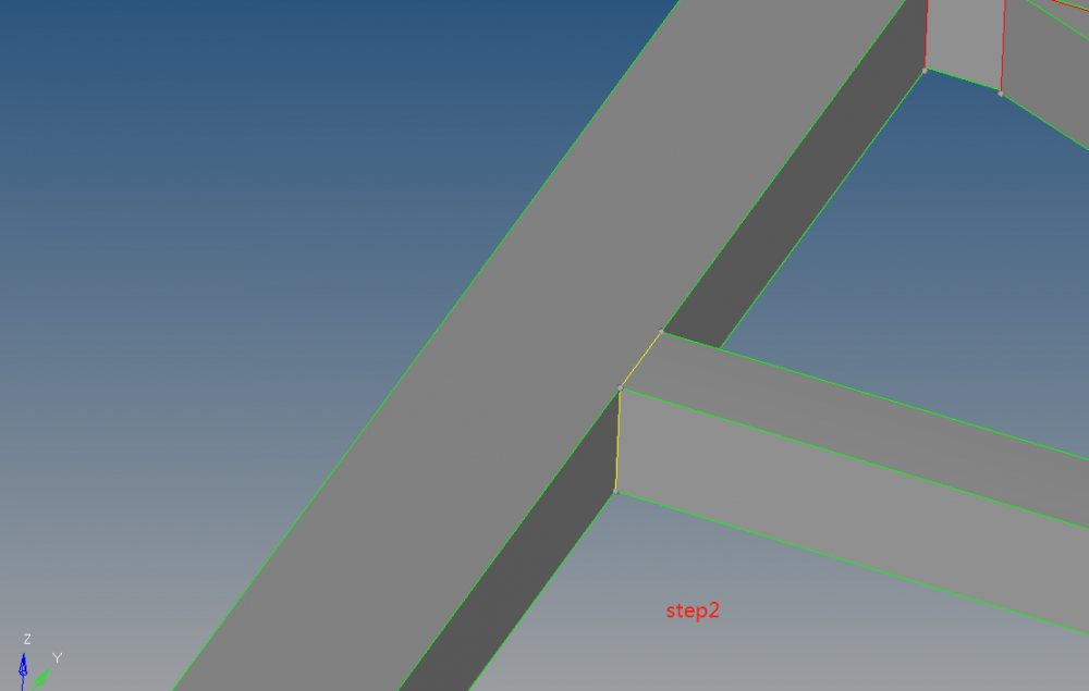
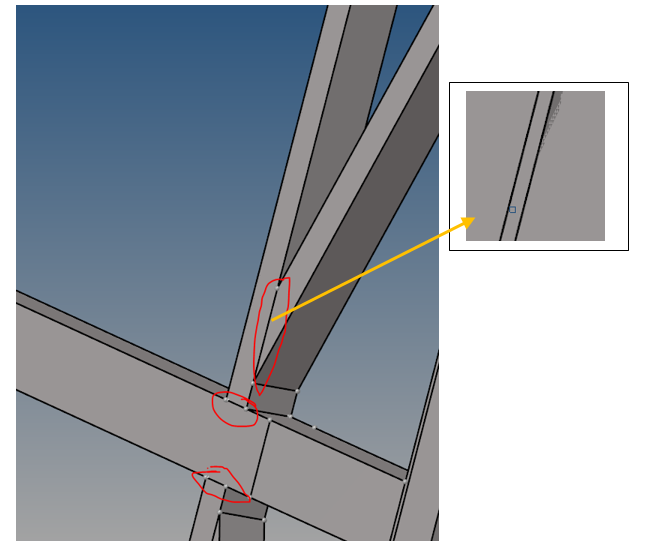
I am a student from China. I do a research of bus body frame, and I have finished the midsurface and repaired the model. Now I want to simulated welding by using common nodes. but I don't know how to repair the gap between the Square tubes(like the picture). The attachment is my model.
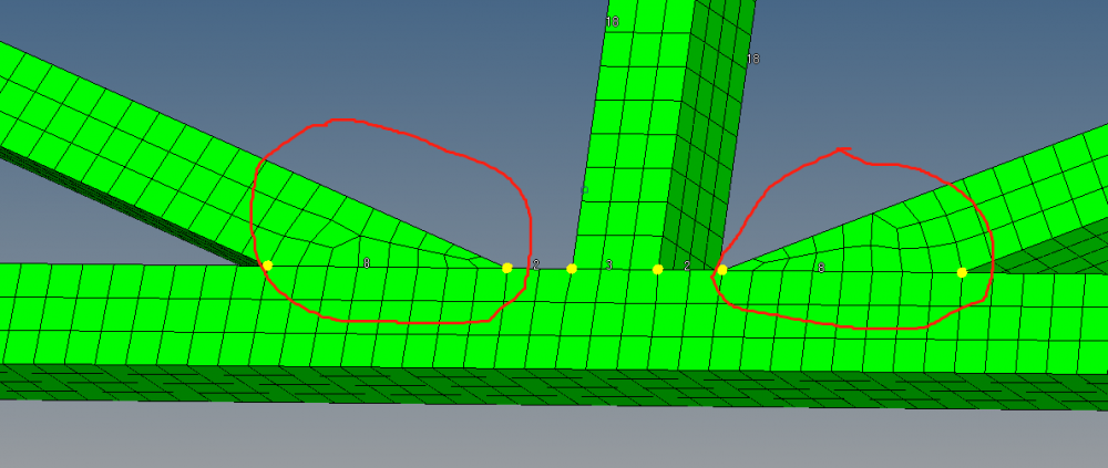
So I sincerely hope to guide me in completing the grid of this model. Thanks in advance!<?xml version="1.0" encoding="UTF-8"?>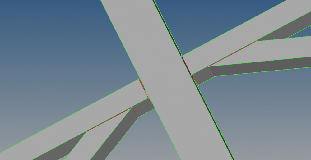
<?xml version="1.0" encoding="UTF-8"?>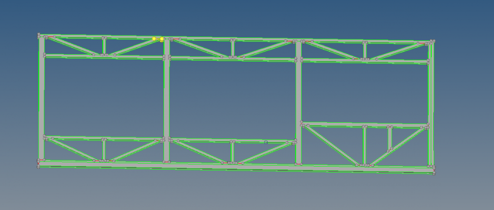
Unable to find an attachment - read this blog