🎉Community Raffle - Win $25

An exclusive raffle opportunity for active members like you! Complete your profile, answer questions and get your first accepted badge to enter the raffle.
Join and Win

I need a VTK format for my mesh

User: "Altair Forum User"
Altair Employee
Updated by Altair Forum User

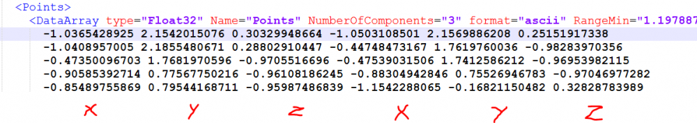
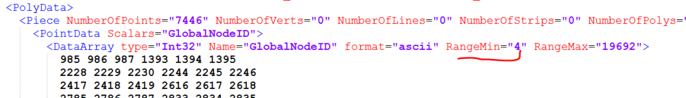
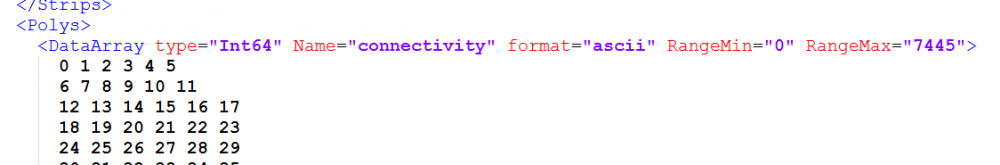
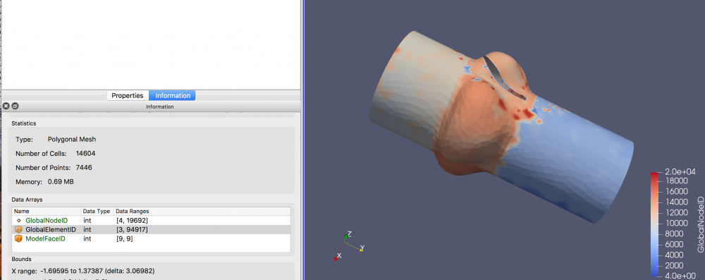
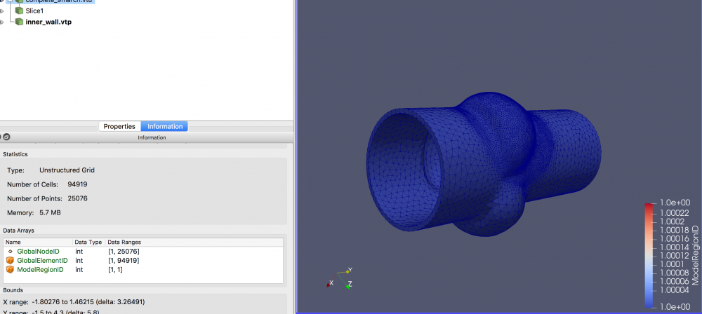
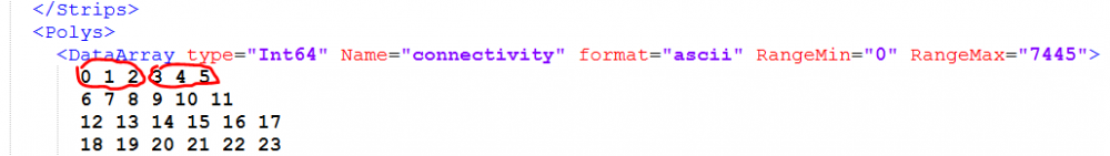
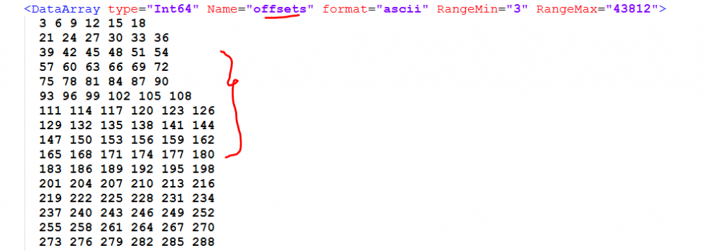
Hi,I am going to work with Fenics to run my problems. Actually, we should have vtk format for my meshes to run Fenics. There is 2 formats for vtk, one is vtp where it is for surface mesh and another format is vtu for volume mesh. I need a code for exporting my mesh to this formats. And for every surface I need a vtp outcome. For example, if I have 10 surfaces, and one volume, I need a code to give me 11 files, 10 files for each surfaces, and 1 file for my volume. Does it make sense? I could pay for this code who want to write it. 

Find more posts tagged with

Sort by:
1 - 30 of 321
    User: "tinh"
    Altair Community Member
    Updated by tinh

    I can make template for that.

    Please describe your vtp and vtu formats

    If it is not so long, it's free for you!

    User: "Altair Forum User"
    Altair Employee
    OP
    Updated by Altair Forum User

    what should I describe for you? I need a vtk files which I can easily open them in Paraview. 

    User: "tinh"
    Altair Community Member
    Updated by tinh

    Could you give me an example of vtk file?

    I think it is a text file that has node coordinates, element definition, isn't it?

    User: "Altair Forum User"
    Altair Employee
    OP
    Updated by Altair Forum User

    I will attach some vtk file that you can easily open it in text file and paraview. . the vtu is volume and the vtp is one of my surfaces.


    Unable to find an attachment - read this blog

    User: "tinh"
    Altair Community Member
    Updated by tinh
    User: "Altair Forum User"
    Altair Employee
    OP
    Updated by Altair Forum User

    yes thats it.

    User: "tinh"
    Altair Community Member
    Updated by tinh

    OK. let's have a look

    I think the template will be simple.

    just I am trying to understand its format, where is node coodinate, node id, element nodes,...etc

    User: "tinh"
    Altair Community Member
    Updated by tinh

    Maybe, coordinates are here, aren't they?

    <?xml version="1.0" encoding="UTF-8"?>Capture.thumb.PNG.3b8b2ea3c30339ea0a6201a7cd374f8a.PNG

    User: "Altair Forum User"
    Altair Employee
    OP
    Updated by Altair Forum User

    yes thats it

    User: "tinh"
    Altair Community Member
    Updated by tinh

    This is clearly node IDs, but I cannot find out number 4:

    what is 'RangeMin'?

    <?xml version="1.0" encoding="UTF-8"?>Capture.thumb.PNG.9a8c30b73a80d4cf0adf2a7dd4d12db5.PNG

    User: "tinh"
    Altair Community Member
    Updated by tinh

    This looks like element definition. Are they hexagon elements?

    And I see, they refer to indices but not IDs of nodes, am I right?

    <?xml version="1.0" encoding="UTF-8"?>Capture.thumb.PNG.d4e7ad59dd383ce0cd4543987c240331.PNG

    User: "Altair Forum User"
    Altair Employee
    OP
    Updated by Altair Forum User

    no there are tetrahedral. and I myself cannot find out the what rangemin is. I am asking my professor to answer me.

    User: "Altair Forum User"
    Altair Employee
    OP
    Updated by Altair Forum User

    <?xml version="1.0" encoding="UTF-8"?>5aa751b3598dc_ScreenShot2018-03-12at9_20_32PM.thumb.png.84fb777f4a457d91a9a1add5baa74d33.png

    User: "Altair Forum User"
    Altair Employee
    OP
    Updated by Altair Forum User

    <?xml version="1.0" encoding="UTF-8"?>5aa75249935f8_ScreenShot2018-03-12at9_23_11PM.thumb.png.a91345a84059dd44de289324eaea88a8.png

    User: "Altair Forum User"
    Altair Employee
    OP
    Updated by Altair Forum User

    this is the surface and the volume mesh that i can see in paraview


    User: "Altair Forum User"
    Altair Employee
    OP
    Updated by Altair Forum User

    that surface is one of my surfaces.

    User: "tinh"
    Altair Community Member
    Updated by tinh

    I see, 

    so the surface is formed by triangle elements? and each of them has 6 node (3 vertices and 3 mid-points)?

    it is tria6 element type in Hypermesh, isn't it?

    User: "Altair Forum User"
    Altair Employee
    OP
    Updated by Altair Forum User

    Yes it is triangle, and No, my mesh does not have middle point

    User: "tinh"
    Altair Community Member
    Updated by tinh

    Ok I see.

    so first 3 indices is for 1st triangle, and so on...

    <?xml version="1.0" encoding="UTF-8"?>Capture.thumb.PNG.7168a82961ac9ca55656645eafd9cd96.PNG


    I am making initial template to check...

    User: "tinh"
    Altair Community Member
    Updated by tinh

    I think we need to couple template with some tcl codes

    because the format is not suitable to be output by pure template...

    User: "tinh"
    Altair Community Member
    Updated by tinh

    Do you know what is 'offset'?

    <?xml version="1.0" encoding="UTF-8"?>Capture.thumb.PNG.2178881707c81f75b4640d4de0d8e4b2.PNG

    User: "Altair Forum User"
    Altair Employee
    OP
    Updated by Altair Forum User

    oh no,  that was my problem too

    User: "tinh"
    Altair Community Member
    Updated by tinh

    I found it,

    the offset field will define type of poly, if it is shifted by 3 => it is triangle element

    But I am stuck with connectivity field, it doesn't refer to global node ids but indices

    and searching how can we generate the indices

    User: "tinh"
    Altair Community Member
    Updated by tinh

    Hi,

    I wrote it. Below proc will help to export vtp, a template is not neccessary.

    example running it from command window of hypermesh:

    p_Export2DToVtpFile MyModel.vtp all; #export all 2d elems

    p_Export2DToVtpFile MyModel.vtp displayed; #export only displayed 2d elems


     proc p_Export2DToVtpFile {FilePath {displayed_or_all displayed}} { 	*createmark elems 1 $displayed_or_all 	*createmark elems 2 'by config' tria3 quad4 tria6 quad8 	*markintersection elems 1 elems 2 	set ElemList [hm_getmark elems 1] 	set ElemNodeList [join [hm_getvalue elems mark=1 dataname=nodes]] 	set ElemNodeCount [join [hm_getvalue elems mark=1 dataname=nodecount]] 	set CompList [hm_getvalue elems mark=1 dataname=collector.id] 	eval *createmark nodes 1 $ElemNodeList 	set NodeList [hm_getmark nodes 1] 	set CoordList [join [hm_getvalue nodes mark=1 dataname=coordinates]] 	set _NodeList [lsort -integer $NodeList] 	set MinNodeId [lindex $_NodeList 0] 	set MaxNodeId [lindex $_NodeList end] 	set _ElemList [lsort -integer $ElemList] 	set MinElemId [lindex $_ElemList 0] 	set MaxElemId [lindex $_ElemList end] 	set NodeCount [llength $NodeList] 	set ElemCount [llength $ElemList] 	set Buffer {<VTKFile type='PolyData' version='1.0' byte_order='LittleEndian' header_type='UInt64'>} 	append Buffer \n {   <PolyData>} 	append Buffer \n {      <Piece NumberOfPoints='NodeCount' NumberOfPolys='ElemCount'>} 	append Buffer \n {         <PointData Scalars='GlobalNodeID'>} 	append Buffer \n {            <DataArray type='Int32' Name='GlobalNodeID' format='ascii' RangeMin='MinNodeId' RangeMax='MaxNodeId'>} 	set Buffer [string map [list NodeCount $NodeCount ElemCount $ElemCount MinNodeId $MinNodeId MaxNodeId $MaxNodeId] $Buffer] 	append Buffer \n $NodeList 	append Buffer \n {            </DataArray>} 	append Buffer \n {         </PointData>} 	append Buffer \n {         <CellData Scalars='ModelFaceID'>} 	append Buffer \n {            <DataArray type='Int32' Name='GlobalElementID' format='ascii' } 									append Buffer 'RangeMin=\'$MinElemId\' RangeMax=\'$MaxElemId\'>' 	append Buffer \n $ElemList 	append Buffer \n {            </DataArray>} 	set _CompList [lsort -integer $CompList] 	set MinCompId [lindex $_CompList 0] 	set MaxCompId [lindex $_CompList end] 	append Buffer \n {            <DataArray type='Int32' Name='ModelFaceID' format='ascii' } 									append Buffer 'RangeMin=\'$MinCompId\' RangeMax=\'$MaxCompId\'>' 	append Buffer \n $CompList 	append Buffer \n {            </DataArray>} 	append Buffer \n {         </CellData>} 	append Buffer \n {         <Points>} 	set _CoordList [lsort -real $CoordList] 	set MinCoord [lindex $_CoordList 0] 	set MaxCoord [lindex $_CoordList end] 	append Buffer \n {            <DataArray type='Float32' Name='Points' NumberOfComponents='3' format='ascii' } 									append Buffer 'RangeMin=\'$MinCoord\' RangeMax=\'$MaxCoord\'>' 	append Buffer \n $CoordList 	append Buffer \n {            </DataArray>} 	append Buffer \n {         </Points>} 	append Buffer \n {         <Polys>} 	append Buffer \n {            <DataArray type='Int64' Name='connectivity' format='ascii' } 									append Buffer 'RangeMin=\'$MinNodeId\' RangeMax=\'$MaxNodeId\'>' 	#append Buffer \n $ElemNodeList; #oh, it doesn't refer to global node ids but indices 	set i -1 	foreach NodeId $NodeList { 		set Index($NodeId) [incr i] 	} 	set Indices {} 	foreach NodeId $ElemNodeList { 		lappend Indices $Index($NodeId) 	} 	append Buffer \n $Indices 	append Buffer \n {            </DataArray>} 	set Offsets {} 	set InitOffset 0 	foreach NodeCount $ElemNodeCount { 		lappend Offsets [incr InitOffset $NodeCount] 	} 	set MinOffset [lindex $Offsets 0] 	set MaxOffset [lindex $Offsets end] 	append Buffer \n {            <DataArray type='Int64' Name='offsets' format='ascii' } 									append Buffer 'RangeMin=\'$MinOffset\' RangeMax=\'$MaxOffset\'>' 	append Buffer \n $Offsets 	append Buffer \n {            </DataArray>} 	append Buffer \n {         </Polys>} 	append Buffer \n {      </Piece>} 	append Buffer \n {   </PolyData>} 	append Buffer \n {</VTKFile>} 	*clearmark nodes 1 	*clearmark elems 1 	*clearmark elems 2 	set fpt [open $FilePath w] 	#fconfigure $fpt -encoding utf-8 	puts $fpt $Buffer 	close $fpt 	set FilePath }


    User: "tinh"
    Altair Community Member
    Updated by tinh

    Hi

    any reply, @rsoltany?

    Is the proc working well?


    I tested its output with paraview, it's ok

    User: "Altair Forum User"
    Altair Employee
    OP
    Updated by Altair Forum User

    Thank you so much, it helped me alot, but what about the volume mesh which has vtu format?


    User: "tinh"
    Altair Community Member
    Updated by tinh

    Do it your self, base on my script

    User: "Altair Forum User"
    Altair Employee
    OP
    Updated by Altair Forum User

    thank you so muchh. 

    User: "Jesús Ramos_21865"
    Altair Community Member
    Updated by Jesús Ramos_21865

    Hello @, first of all thank you very much for your work, I know this is very late but I really need to export a surface mesh to VTK and I can't seem to get your script to work, I have copied the script you pasted, pasted it onto a notepad and saved it with a .tcl extension.

    I have opened it with HyperMath and have separated all the lines, I am uploading the result here (I have uploaded it with a .txt extension so that it will allow me to upload it).

    I have then tried to run the command you posted on the command view of Hypermesh (making sure I was in the correct folder) while my mesh was open, but I get the error "hm_getvalue: Mark is empty."

    Am I missing any steps? Is the file I uploaded correctly modified? Is the extension .tcl ok or does it need to have a different extension?. Thank you very much for your help.

    User: "QuyNguyenDai"
    Altair Community Member
    Updated by QuyNguyenDai

    Here's my script to export shell mesh into VTK/VTU format :

    image

    image


1 - 30 of 321