🎉Community Raffle - Win $25

An exclusive raffle opportunity for active members like you! Complete your profile, answer questions and get your first accepted badge to enter the raffle.
Join and Win

Flanging and Holes punching

User: "Altair Forum User"
Altair Employee
Updated by Altair Forum User

Hi everyone,


I am new to HyperWorks or more specific is Hyperform.


1. The flanging tools need to create manually in other CAD software or the software itself can create automatically?


2. How to define the hole punching in Hyperform? Using trim? Possible import tools to create holes?


3. How to create trim lines automatically or manually in Hyperform? 


Thank you.

Find more posts tagged with

Sort by:
1 - 4 of 41
    User: "Altair Forum User"
    Altair Employee
    OP
    Updated by Altair Forum User

    Hi GMCobraz


    1. yes you need to design the tools in CAD s/w 

    2. You need to run trimming operation in HF. Its a preprocessing step and doesn't involve Radioss solver.

    In HF-Die module you can generate the trim line and export only the trimline as .iges file.

    User: "Altair Forum User"
    Altair Employee
    OP
    Updated by Altair Forum User

    Thanks for the reply.


    How am I going to get the flange tools position correct? Using trim lines as reference or well assembly those tools in CAD software before import into Hyperform?


    Thank you very much.

    User: "Altair Forum User"
    Altair Employee
    OP
    Updated by Altair Forum User

    Hi everyone,


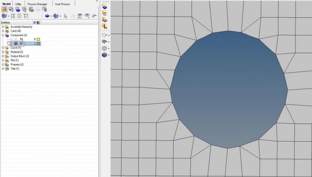
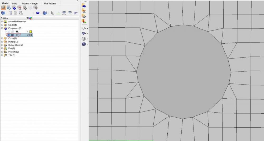
    Below two pictures are holes punching using trimming.


    I want to ask why in first picture seems like I not successful trim the hole but seems successful trim in second picture?


    Thank you.

    <?xml version="1.0" encoding="UTF-8"?>post-34041-0-53723600-1416478975_thumb.j

    <?xml version="1.0" encoding="UTF-8"?>post-34041-0-90286400-1416478979_thumb.j

    User: "Altair Forum User"
    Altair Employee
    OP
    Updated by Altair Forum User

     You generate the trim line for the blank as igs file. in cad s/w he can use it a reference to create and position the tools.