Hi,
I am performing an analysis of an infinite multilayer substrate (Plane / Ground) (Planar Greens function).
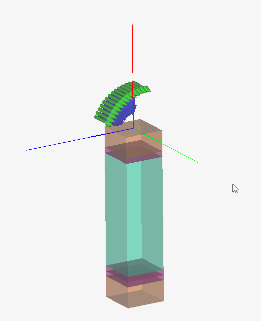
I have a Plane Wave Source with Theta=0-60º, and frequency set from 10-21GHz.
Request: Transmission / Reflection.
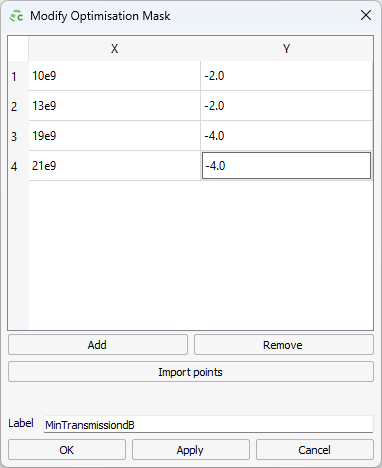
I am trying to optimize layers thickness in order to maximize the transmission coefficient. I created a mask of allowed loss (dB) per frequency:
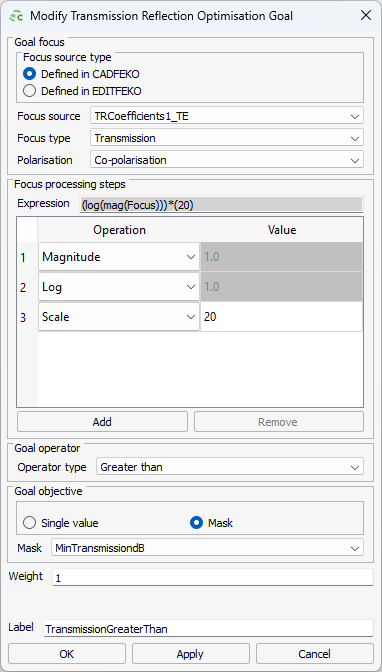
And a transmission goal to be greater than that mask:
After running optfeko, if I plot the mask in postfeko, it shows a independent X variable (X axis of the graph) from 0 to 1. I was expecting it to be the frequency range set in the table. So, I am not sure if it’s internally applying the mask correctly (per frequency).
The question is:
How does feko know that the X values in the mask table refer to frequencies and not to angles?
P.S.: Even if I set a Single incident wave angle (so that the only varying variable transmission depends on is frequency), it still shows the mask in postfeko with the horizontal axis from 0 to 1.
Thanks

