The Siemens Community Catalyst program was co-created with our community to acknowledge technology leaders who consistently contribute to the Siemens Community. Nominations are accepted on a rolling basis.
Hi
I have received this error in Feko while I wanted to check the current stimulation on a patch antenna with Prob Fed:
'Error 16030: Does not contain axes which can be plotted on a 3D view'
How can I fix it?
Thanks
Hi Emily
Sounds like an error from POSTFEKO?
Please attach your model, else some screenshots would help.
Same problem.
Unable to find an attachment - read this blog
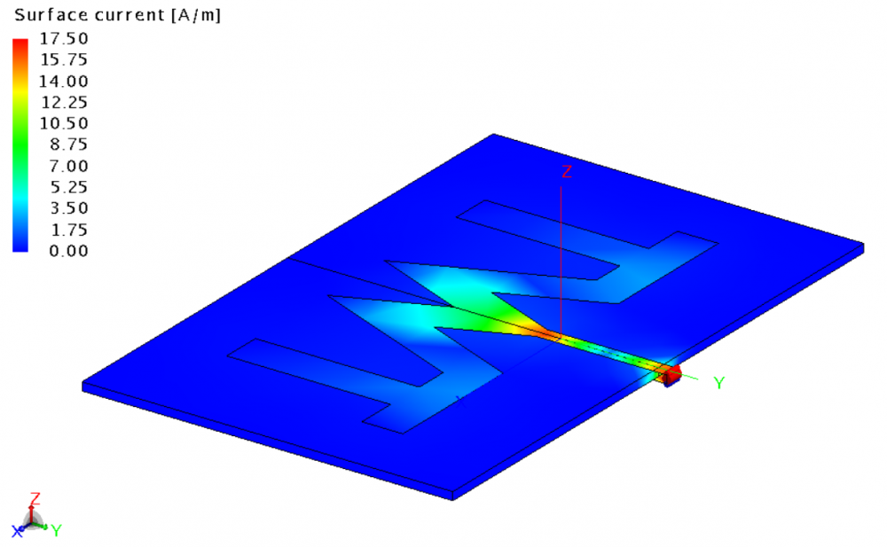
my current distribution is odd as well.
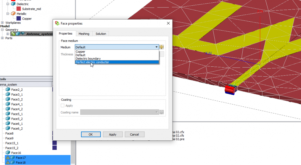
The two faces below are set to dielectric properties, not copper.
Change them (to copper I presume) as shown in the below image and rerun.
I still cannot reproduce the POSTFEKO error. If you still get the error after the changes, please provide a screen shot.
<?xml version="1.0" encoding="UTF-8"?>
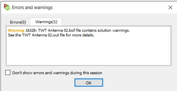
When I run the FEKO Solver, these warnings and notices popped up. Will they affect the results?
This too - after the POSTFEKO loaded.
If you specify a too large thickness for the lossy metal, the warning will appear. Results could be wrong, but it's difficult to say how wrong. Might be worthwhile to compare with a PEC solution.
The str file is the file storing the solution. It is sometimes re-written. No need to worry about that.
Regarding the original error reported in this thread, this error can be triggered in POSTFEKO if the result cannot be plotted on the 3D view. For example, in your model @ebdaculan, the far field cannot be plotted on the 3D view because it contains a single point only. If you increase the number of points in the far field request, the far field pattern can be plotted. Did you get this error when plotting currents? I have not managed to reproduce the error when plotting the currents for your model.
The current plot is actually odd - but no error was reported. How do I increase the number of points in the far field request?
Thanks.
If you specify a too large thickness for the lossy metal, the warning will appear. Results could be wrong, but it's difficult to say how wrong. Might be worthwhile to compare with a PEC solution. The str file is the file storing the solution. It is sometimes re-written. No need to worry about that.
I have clicked DEFINE in CADFEKO and set MODEL UNIT in millimeter. The thickness of the lossy metal is set to 35e-3. Does that mean 35e-3 millimeters or 35e-3 meter?
The thickness value of 35.3e-3 when you have set the model unit to mm means 35.3 micro meters thickness.
Modifying/setup of far field requests are covered in the Example Guide, part of your Feko installation.
thanks
Join us for a community conversation on how High-Performance Computing (HPC) and Simcenter PSIM work together to meet the increasing demands of modern power electronics simulation. During this one-hour technical session, you'll discover how leveraging HPC can speed up simulations, improve scalability, and empower engineers…
Join us for a community conversation on accelerating your motor simulation workflow with Simcenter Simlab. In this beginner-friendly session, we'll introduce the platform's automated model-building capabilities and show how easy it is to set up your first electric motor analysis. You'll see the basic steps of geometry…
Join us for a Community Conversation where we'll discuss practical approaches to analyzing complex electromagnetic models using hybrid solver techniques. This session will provide a general overview of how different computational methods can be combined within a single simulation to address models containing varied…