CFAST ORIENTATION

Altair Forum User
Altair Forum User
Altair Employee
edited October 2020 in Community Q&A

Hello,


When creating cfasts using the following command:

1D > connectors > spot > type CFAST ELEM (GA-GB) 

I select all the nodes imported from the cad model, then I select all the components of the model.


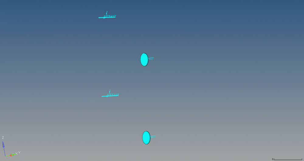
This creates all the cfasts but, when viewing them in 1D Detailed Element Representation, some show the orientation axis, while others show the detailed representation.

Is this because the connectors are not alligned correctly?
How can I correct the orientation?


Thanks for your help.


N.

<?xml version="1.0" encoding="UTF-8"?>CFAST_VIEW.png
Tagged:

Answers

  • Altair Forum User
    Altair Forum User
    Altair Employee
    edited September 2018

    In the pictures below,  I created a ocnnection between the upper, middle and lower components.


    In the spot options i selected '2 sys per layer' and 'use normal direction of the closest element to determine links'.


    In the first connection, the systems don't have the same Y direction. But, after performing the connection between the middle and lower components, the first connection is corrected (both systems have the same Y direction), but that does not happen for the second one. 

    <?xml version="1.0" encoding="UTF-8"?>CFAST_VIEW_01.png

    <?xml version="1.0" encoding="UTF-8"?>CFAST_VIEW_02.png

  • Altair Forum User
    Altair Forum User
    Altair Employee
    edited September 2018

    When I check the element cards of the cfasts, they do not mention these axis systems, and when I export the model in bdf and open it, these axis systems are not referred in any element, or property.
    Is this only a graphical problem?