Flow Simulator (FS) can automatically create some flow elements directly from CAD geometry. This discussion describes the methods, features, and limitations of this useful tool in the FS user interface (UI).
Introduction
FS is a tool that can be used throughout the design cycle. Preliminary design studies can be conducted using rough sketches of a flow network. As the design matures and CAD geometry becomes available, it can be loaded into the FS UI to accelerate flow network creation or assist in network visualization. If the pipes are circular, FS can be used to automatically create tube, bends, expansions, and contraction elements.
CAD Geometry
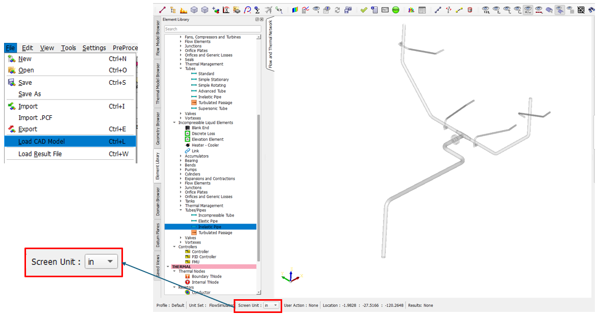
FS can load CAD geometry in IGES or STEP file format. FS only loads curve and surface information since this is the most useful for geometry visualization and element creation. Solid bodies and points are not loaded.
IGES and STEP files contain information about the length unit (inch, meter etc..) of the geometry. The FS UI uses this length information to set the “Screen Unit”. The Screen Unit is used in any function using CAD geometry. These functions include element creation, cavity surface point selection, and geometry measurement. It is recommended not to change the Screen Unit to something other than the CAD file length unit. Also, use a length unit to keep the dimensions to a reasonable range (.01 to 100) since the FS UI may not display text at an appropriate size for very large or small models.
Flow Element Creation
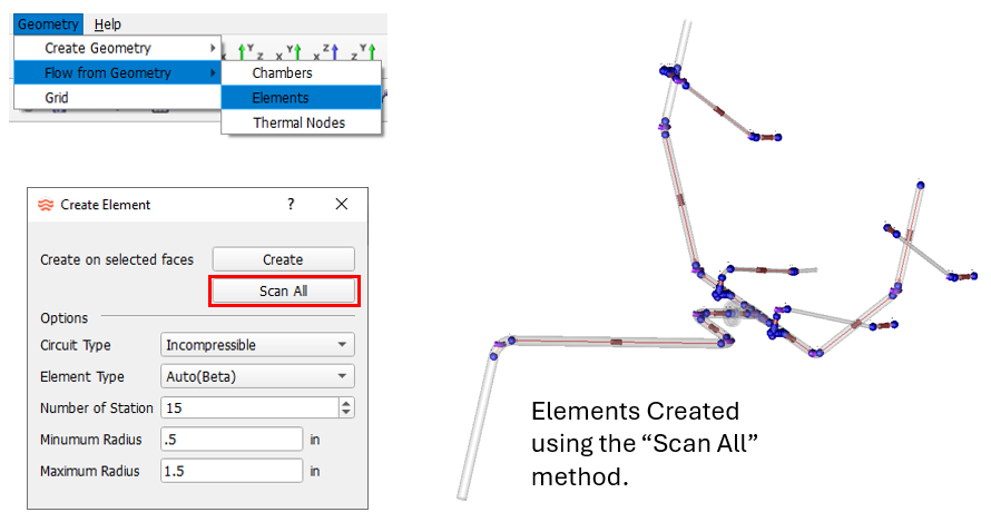
CAD geometry of circular cross-section piping networks can be used to automatically create flow elements. The “Scan All” option will create elements with little user input, and it is a good tool to try first and see how it works for your problem. Always pick the type of flow elements to create, compressible or incompressible, before continuing. A radius range can be given to limit which geometry surfaces are used to create elements.
Elements can also be created one at a time. Use the “Create” key to pick each circular surface where you would like to create an element. Click “Create” and CAD turns color indicating it is time to start picking surfaces for element creation.
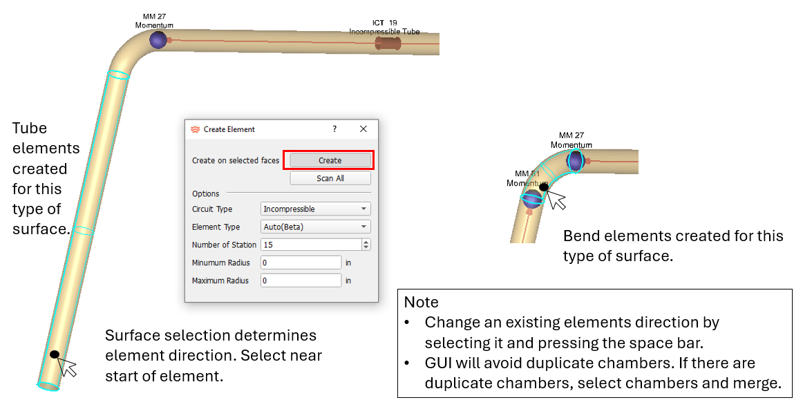
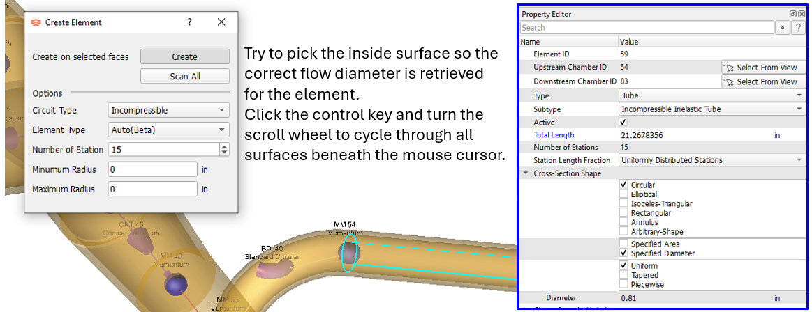
The GUI will extract some flow element geometry from the surface used to create an element. Tube length and diameter or the bend radius and angle are extracted. It is still recommended that these inputs are checked for each element.
One more method to create an element on a surface is to drag an element from the element library onto the modeling window, then press the “alt” key. CAD Surfaces will then become selectable. Just select the surface where you want the element, and it will be created.
Flow Chamber Creation
If the element creation method is not successful, the CAD geometry can be used to create flow chambers, and the elements can be created manually. With this method, the flow chambers are at least in a good location on the geometry.
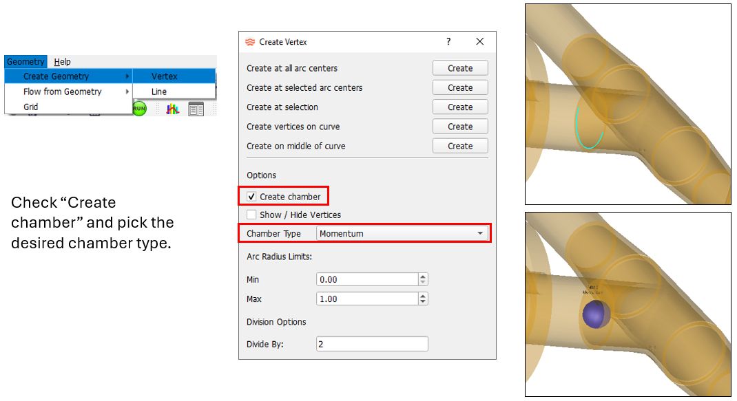
If “Create chamber” is not checked, a vertex (i.e. geometry point) is created. The vertex can be used to locate elements and chambers. Drag an item (usually a chamber) from the element library and press the “shift” key. The existing vertices will become visible. Drop the item on the appropriate vertex. An existing chamber can be moved to a vertex by selecting the chamber and pressing the “v” key.
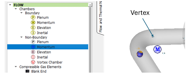
Vertices are temporary and will not be saved with the model. They will be lost when the model file or UI is closed.
Limitations
The automatic element creation tools work best for circular cross-section piping. Arbitrary shapes do not currently work to create elements, but they can be helpful for chamber location.
Element types that are automatically created are restricted to the types typically found piping networks (tubes, bends, expansions, contractions). Junctions are not automatically created.
