Introduction:
MotionSolve offers different approaches to define expressions that can be used to specify properties of many mechanism entities.
The different ways explored are:
- Use a MotionSolve expression and then define it directly in MotionView through the expression builder.
- Use co-simulation with Twin Activate, where the expression is defined in it.
- Use an FMU that is created in Twin Activate, where the expression is contained.
- Use a subroutine, in Compose language, where the code defines the equivalent expression.
The example model:
This document uses an example model of a simple 4 bar mechanism where the expression is used to define the rotational motion law applied to the revolute joint of the short left bar of the mechanism:
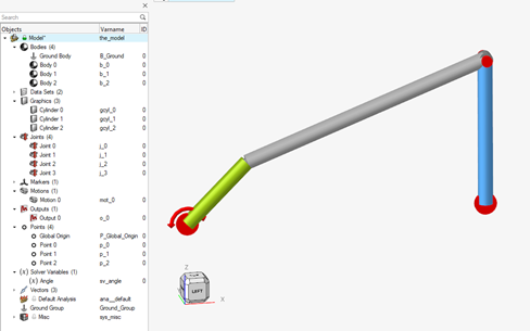
In the model, there are 3 bar bodies defined, joined according to the 4 bar mechanism and the motion property is defined through the value of a solver variable (Angle).
To check the model, the same variable is also used as the first component (F2) of an output (Output 0).
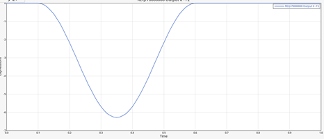
The proposed law, time dependent, has these characteristics:
- Before 0.1sec is null
- Between 0.1 and 0.6 is a cos wave, with mean value -1 and multiplied by PI (PI-Greco).
- After 0.6sec is null
The expression has a shape like this:
All the example models are provided in the attached zip file that contains:
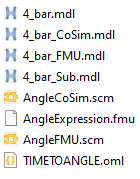
- 4_bar.mdl is the MotionView model to start with when the MotionSolve expression approach is used.
- 4_bar_CoSim.mdl and AngleCoSim.scm are the MotionView and the Twin Activate files for the Co-Simulation approach.
- 4_bar_FMU.mdl, AngleExpression.fmu and AngleFMU.scm are the MotionView, the FMU file and the Twin Activate files for the FMU approach.
- 4_bar_Sub.mdl and TIMETOANGLE.oml are the MotionView and the Compose files for the subroutine approach.
1 - Use MotionSolve expression:
One of the most important aspects of MotionSolve is the large library of functions that can be used in the model, as described in Functions (altair.com).
These functions are also supported by the Expression Builder in MotionView that makes it easy to write the expression that can be used to define properties of entities like motion, forces, spring characteristics, specific outputs, and many more.
It is important to note when talking about MotionSolve expressions, is intend Run-Time expressions, so expressions solved by MotionSolve, during the solve phase, and not Design-Time expressions, who are solved by MotionView, used to parameterize the model at the initial configuration.
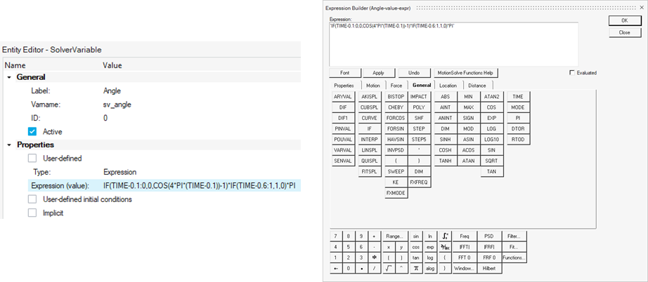
In this case, the expression used for the solver variable Angle (that can be composed through the Expression Builder) will be:
- `IF(TIME-0.1:0,0,COS(4*PI*(TIME-0.1))-1)*IF(TIME-0.6:1,1,0)*PI`
The General tab allows access to the IF, TIME, PI, COS functions to define the Angle solver expression:
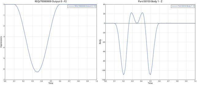
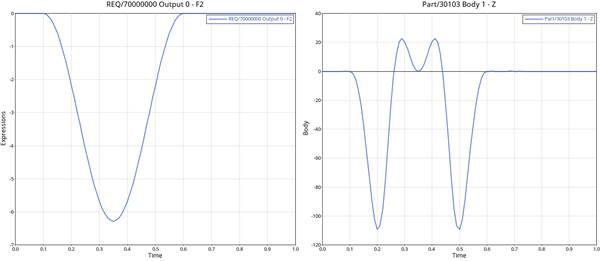
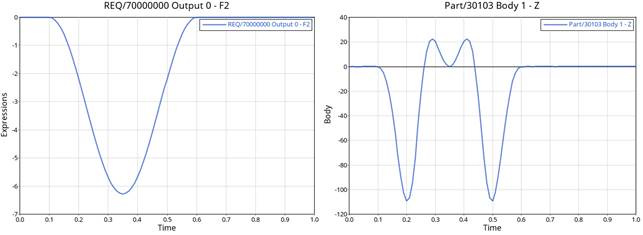
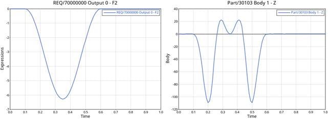
After the run (all is already set on the example model, the duration is 1sec), you can check the results in terms of Angle value (Output 0àF2) and for example vertical (Z) displacement of the Body 1:
Reference file: 4_bar.mdl.
2 - Use co-simulation with Twin Activate:
Different tools can be used for co-simulation, but Twin Activate is the most integrated tool to control the mechanism solved by MotionSolve.
Before we proceed, we need to prepare the mechanism model with the right input/output signals for the simulation, then we need to organize these signals into a Plant Input array and a Plant Output array.
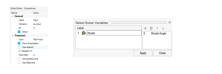
In MotionView, the input signal (provided by Twin Activate) is the Angle solver variable already defined in the model. Then for this signal, we need to place it into a plant input array, that can be named Input:
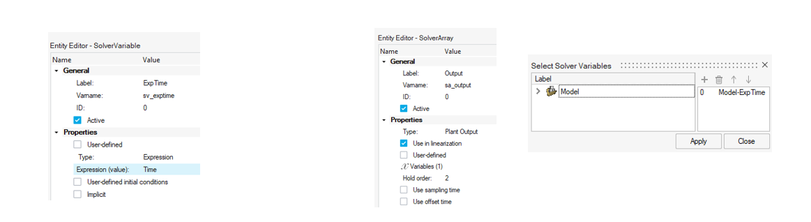
The output signal will be the simulating time. Sometimes this does not need to be exported, because during the co-simulation it is implicitly defined. In any case, we can define a solver variable (ExpTime), with TIME as the expression and then use this solver variable in the Plant Output array that can be called Output:
After that the MotionView model (then the MotionSolve model) is ready for co-simulation and then can be saved (4_bar_CoSim.mdl).
Now it is time to define an Activate model to run with this MotionView/MotionSolve model.
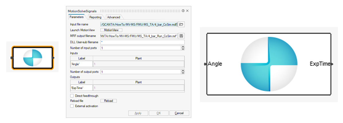
In Twin Activate, add the MotionSolveSigna block, that permits us to directly use the MotionView model (or the MotionSolve model if is already available) and is identifying the input/ouput signals. To point to the .mdl file, set the MRF output filename to your preferred naming convention.
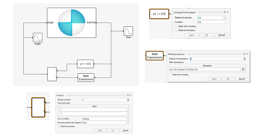
Then we need to define the expression. For example through these blocks:
- Math Expressions block where we define the cosinusoidal expression, for time >=0
- CompareToConstant block to set value 0 for time >=0.6sec used in the Product block to null the Math Expression value.
- Just to check, is it possible to put Scope block to plot the values of the input/output.
So, the model and the blocks are:
Set initial time 0sec and final time 1sec then run from Twin Activate.
To check, are available the result files of MotionSolve, that can be used to plot the Angle value (Output 0àF2) and the vertical (Z) displacement of the Body 1:
Reference files are: 4_bar_CoSIm.mdl (MotionView) file and AngleCoSim.scm (Twin Activate).
3 - Use an FMU:
FMU can be used in a mechanism model set through MotionView and used by MotionSolve.
FMUs can be created in different tools, in this case it is defined in Twin Activate from the co-simulation model.
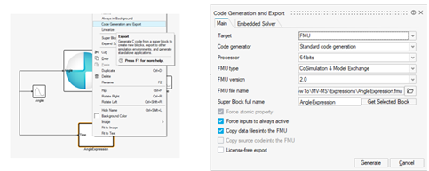
The FMU is created by selecting the expression blocks and creating a SuperBlock that can be exported.
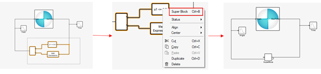
For better comprehension, the super block can be renamed to AngleExpression resized and set, and renamed to be the input/output ports to Time and Angle.
To create the FMU file, select the super block in the options use Code Generation, where you can select the FMU as the target, with the right name and then generate the file.
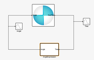
The MotionView model is modified by adding an FMU entity that uses the generated FMU file, and as input, uses the TIME variable.
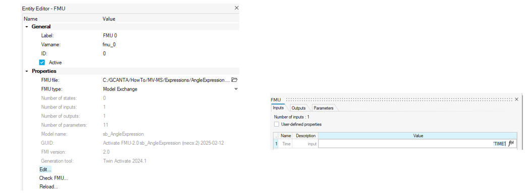
Update the solver variable Angle, to use the output from the FMU entity.
Run the model and check the results as before:
Reference files are: 4_bar_FMU.mdl, AngleFMU.scm and AngleExpression.fmu
4 - Use a subroutine:
Another helpful functionality of MotionSolve is the possibility to use subroutines to define the properties of many entities, like solver variables (as is this example), forces, spring-dampers, motions, outputs and many more.
Many different subroutines can be used as described in The Subroutine Interface for MotionSolve (altair.com).
In this example, the subroutine is used to set the value of the solver variable Angle through code in the Compose language.
In Compose, the code can be created like this:
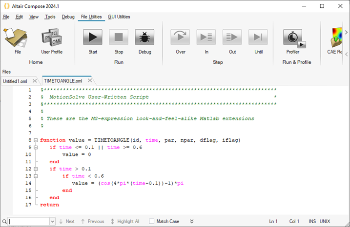
In this case, the time variable can be implicitly used. Make sure to use the same filename as the function name when saving the Compose model. So save the Compose model as TIMETOANGLE.oml.
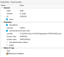
Inside MotionView, modify the solver variable Angle to User-define, set the function type to COMPOSE, the local file to the Compose model (TIMETOANGLE.oml) and the function name as the function name (TIMETOANGLE).
Verify the results as usual:
Reference files are: 4_bar_Sub.mdl, TIMETOANGLE.oml
Recap:
The scope of this example is to show how an expressions can be defined in different ways depending on the source and the complexity of the expression. In fact an expression already defined in other tools can be used in the model, through FMU, Subroutine or integrate the mechanism into another tool like the case of co-simulation.
An additional possibility is to use an expression to convert the mechanism into a FMU and use it in the tool where the expression is defined.
Also complex expressions can defined directly in the model due to the large library of functions of MotionSolve and the support of the Expression Builder inside MotionView.
Don’t hesitate to contact Home - Altair Community for more information.
