Troque becoming unstable when changing the weight of the motors

Hi
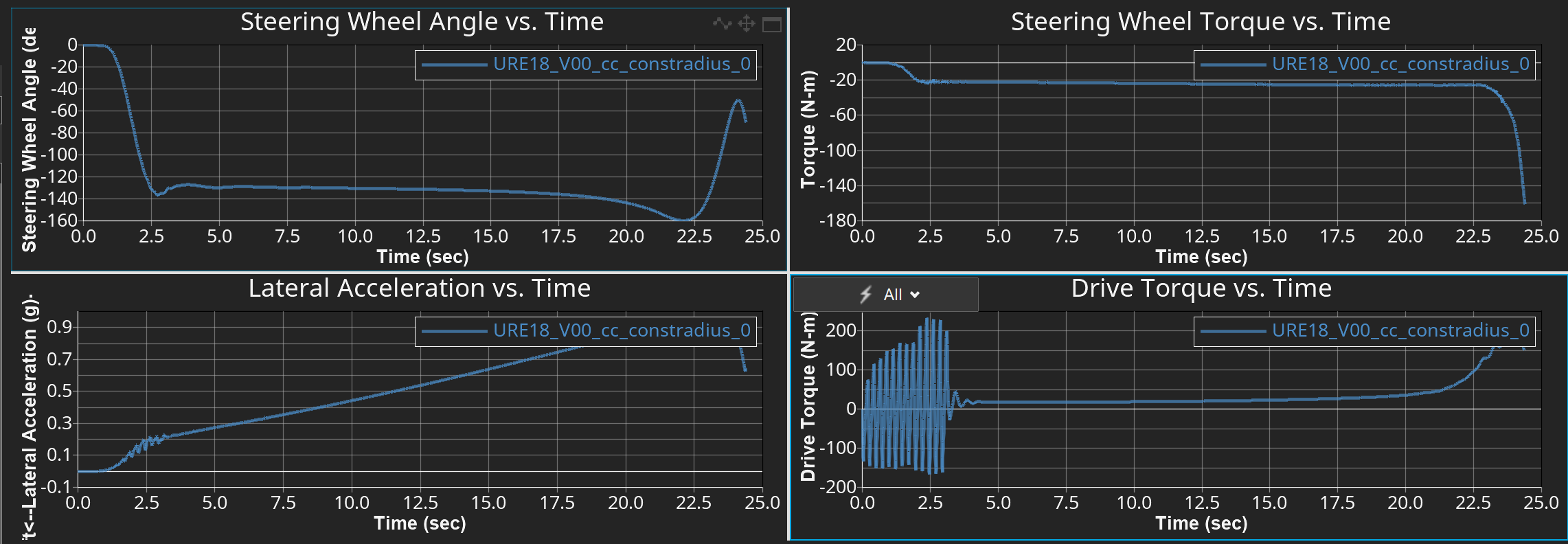
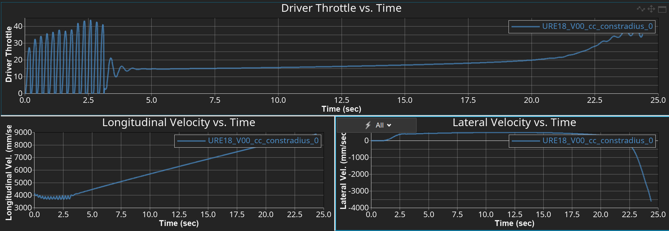
I have modified a full vehicule with driver to the car we are trying to simulate. Everything works fine until I change the weight of the electric motors, the torque becomes unstable. The simulated event is constant radius, this only happens on the straight part of the constant circle; once the turn starts, the torque stays stable. This disturbance can also be seen in the force acting on the suspension. Any clue as to why this is happening?
Thanks in advance
Bollow the plots I get of the event
Best Answer
-
Hi @MBURE,
You are correct. Since this was an example model, I did not modify the mass of each 'engine' which is currently set to 200 kg each. With the total mass of your vehicle currently at 676 kg and two motors limited to 15 Nm of torque, it looks underpowered. If we reduce the mass of each Engine/Trans body to 1 kg, then your vehicle mass drops to 278 kg.
With the reduction in mass alone in your model, we can see the throttle demand is still at 100%:
However, the longitudinal velocity increases over time:
With some additional modifications to the peak motor torque, you will likely achieve the expected performance.
Next time make sure to check the overall mass and motor properties of your vehicle before running the events.
Hope this helps,
Adam Reid
0
Answers
-
Hi @MBURE,
If you are significantly changing the mass of the overall vehicle, then the properties of the eMotor may need to be updated. You can find the various Data Sets here:
Additionally, the driver signal smoothing frequencies may need to be adjusted. You can find those fields here:
I would also review the outputs for the Throttle Demand and Wheel Omega, to see if the Driver Model is in fact requesting this fluctuating torque or if the vehicle is unable to process it.
Hope this helps!
Adam Reid
0 -
Hi?
The smoothing frequency helped indeed but didn't solve the complete problem but is now only present in the first seconds. I tried to change a bit the parameters from the motors but couldn't do much because it is mainly loading in propretiefiles, which we haven't made yet, and we were hoping to solve this at a later stage once all the rest works. As well, I saw you are using a single motor while we use a dual, but that shouldn't change anything, I assume.
For the throttle demand, I couldn't find anything about it, only the throttle output from the driver (which I added in the previous comment). For Wheel Omega, I don't really understand what it represent and how I should interpret the outputs
Thanks for the help
Have a nice day.
0 -
Hi @MBURE,
I'm glad the smoothing frequency helped.
I believe that in the original run, the initial vehicle velocity is not the exact value that was desired and so the Driver Model reacted to decrease the measured error. However, if your eMotors are using default properties from a much larger and heavier vehicle, but this is implemented in a much smaller FSAE car, then there may simply be too much power available.
The wheel omega is simply the wheel rotational velocity. It would show if you have wheel spin occurring or not. If there is not enough traction, then that could also explain why the throttle is reacting so drastically: the increase in throttle was not proving the expected increase in longitudinal speed.
Regardless, it looks like for this event the unexpected behaviour happens at the beginning of the event, whereas the important limit handling happens at the end of the event. I would not spend too much time fine-tuning the event beyond these smoothing frequencies, as it looks to has done the job.
Hope this helps!
Adam Reid
0 -
Hey,
I started changing the weight of other bodies, and it also made the torque unstable again. I tried modifying existing ones given by Altair for the motorproprepreties to make them less powerful, but it loads them in as a txt-file, and I am not able to keep them as efmp files. This results in a non-working simulation. How can I modify these files? What I also don't understand is why when we change the weight, the torque is being impacted. I understand it changes the forces acting on the car, but it shouldn't influence the torque. As well, what is weird is that it is unstable in the straight, but once it starts cornering, it is stable again. Also, only the "NissanLeafEfficiencyMap" has stability during the cornering.
I also had another question: isn't it possible to just define a steering angle and a constant torque instead of having the driver calculate all this in function of the path? This would maybe prevent this instability?
Thanks for the help.
Have a nice day
0 -
Hi @MBURE,
The straight line stability of this vehicle model will be impacted by several factors:
- The maximum torque of the powerpack:
- If you are using a high torque property file but for a FSAE vehicle, which is considerably lighter than anything it was designed for, then a twitchy throttle response will cause the vehicle to break traction.
- That would explain why the Nissan Leaf property file does not cause issues while the 320kW property file would be unstable.
- I would assume that if you plotted the wheel omega (rotational velocity) you see the wheel speed spike but the longitudinal speed of the vehicle stay steady.
- It looks as though you are trying to complete steady state events, so you do not need this higher definition system that you do not have a full set of inputs for.
- Simply replace the electric motor system with the Linear Torque Map Powertrain system (the default) which only needs a maximum and minimum torque.
- Modify it as needed with respect to the number of bodies, etc., but this simplified logic will make it significantly more stable for your vehicle.
- Your tire models: if you are using a tire model that can not support the large amounts of torque being requested from the Driver Model, then you will have significant wheel slip and cause the throttle response to be erratic. Please use a tire model that has been sized properly and not simply scaled from one in our generic database.
- Your initial straight length: if it takes a while to stabilize, simply give it more room to do so. increase the initial straight length until it is nice and smooth. Again, the straight portion of a constant radius lateral accel event is not the focus of this event, however.
If you use the standard FSAE vehicle from the FSAE library, you can see it features the Linear Torque Map Powertrain system, and the results are very smooth (see below). I adjusted the speeds to be similar to what I can guess with yours (15 kph start, 40 kph final) but had to guess at the dimensions (20m initial, 20m radius)
Hope this helps!
Adam Reid
0 - The maximum torque of the powerpack:
-
Hi,
Yes but we use electric motors and 4-wheel drive. While here it seems to be a pertrolum motor and 2-wheel drive.
We have the data to make an efmp file, the problem is that when I make one, it only loads it in as txt and not as efmp so how can I create such a file.
As well what are the units of the values in the next picture? I tried with what you said of using a linear Torque map powertrain system by copying it form the formula student library but now the car doesn't even want to turn anymore. While I only replaced the electric engine.
Thanks in advance for the help
Have a nice day
0 -
Hi @MBURE,
- That's fine, just implement two Linear Torque Map Powertrain systems if you are trying to keep the 4WD layout. I understand you are looking to replicate an electric 4WD system, however the point I am trying to make is that you can significantly simplify your model at this stage of development until you better understand MotionView. Rather than calculate the output torque from the electric motor based on a large property file and complex calculations, you can calculate the output torque from a simplified system that more-or-less uses a linear lookup table.
- Copy an existing EFMP file, modify it as needed, then load it into your model
- Torque is measured in Nmm.
Looks like you have not integrated the powertrain system into your model properly. To help some more, I created the following model to better explain my suggestions:
I duplicated the Rear Diff and Halfshafts system and assigned it to the front wheels. I duplicated the Linear Torque Map Powertrain system and assigned it to the new front diff and halfshafts system. I lowered the peak torque for both 'motors' to 15 Nm. As you can see in the results, the speed outputs for longitudinal velocity and wheel speeds are stable and the event is completed as predicted.
Please use this model as a guide to correct your errors in either the original model and/or your new model.
Hope this helps!
Adam Reid
0 -
Hi,
Thanks for the clear explanation, and it is what I also did, but for an unknown reason I still get error's. I added the model so you could see why. As you can see in the picture, it seems like some data from the driver isn't correct, but I can't change anything from the driver (see picture); nothing is being displayed in the entity editor. So how am I supposed to change that?
Have a nice day
0 -
Hi,
Discard my last message. I just closed my computer and started it, and it worked again.
But I got another problem. The vehicle speed decreases. I checked all the connections, and this shouldn't happen. I added the model so you could look into it.
Have a nice day
Thanks for the help
0 -
Hi @MBURE,
You are correct. Since this was an example model, I did not modify the mass of each 'engine' which is currently set to 200 kg each. With the total mass of your vehicle currently at 676 kg and two motors limited to 15 Nm of torque, it looks underpowered. If we reduce the mass of each Engine/Trans body to 1 kg, then your vehicle mass drops to 278 kg.
With the reduction in mass alone in your model, we can see the throttle demand is still at 100%:
However, the longitudinal velocity increases over time:
With some additional modifications to the peak motor torque, you will likely achieve the expected performance.
Next time make sure to check the overall mass and motor properties of your vehicle before running the events.
Hope this helps,
Adam Reid
0 -
Hi,
Yes, sorry, I realized the same and modified it and didn't have the time to write a comment before you answered.
Sorry for this small inconvenience.
Thanks for you fast replies and help
Have a nice day
0 -
Hi,
But what I still find weird is why doesn't he try to accelerate from the beginning of the event? In the previous model, that wouldn't be the case, so what is the reason behind that? Is it just the new motor model that works like that? This isn't a big problem, but I was just wording why.
Thanks in advance
have a nice day
0 -
Hi @MBURE,
The vehicle is only meant to accelerate after completing the straight line portion of the constant radius event. This is demonstrated in the ADF file, where you can see for maneuver 1 that the speed demand is constant:
I am not sure why in your old model the vehicle would accelerate during that portion, unless the initial STATIC simulation failed to find the initial velocity due to model errors and was initialized considerably lower than the target straight line velocity, so the vehicle had to accelerate in the straight to achieve the intended speed.
Hope this helps!
Adam Reid
0