Question Regarding Mesh size

mraei047
mraei047 Altair Community Member
edited October 2020 in Community Q&A

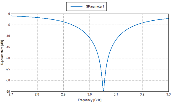
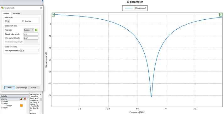
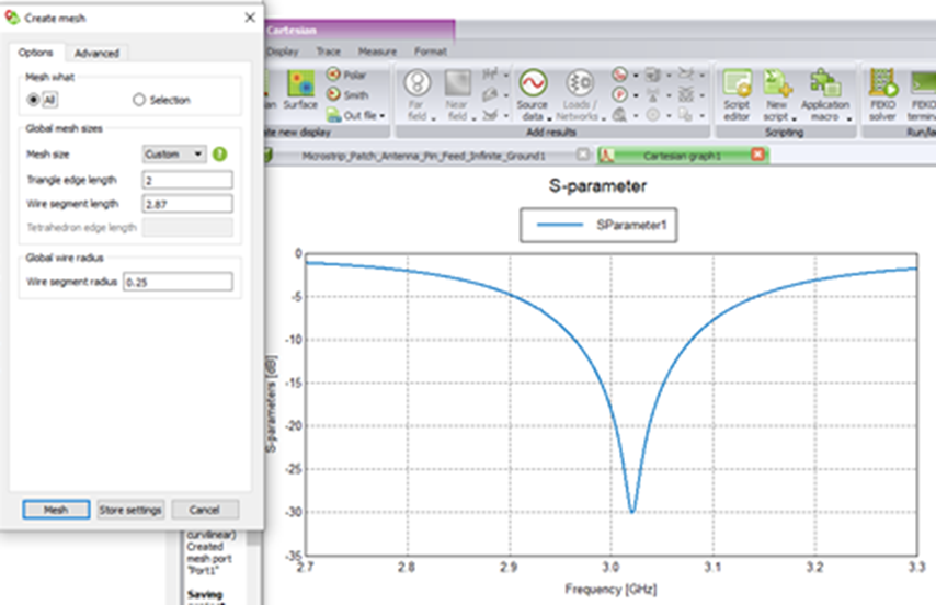
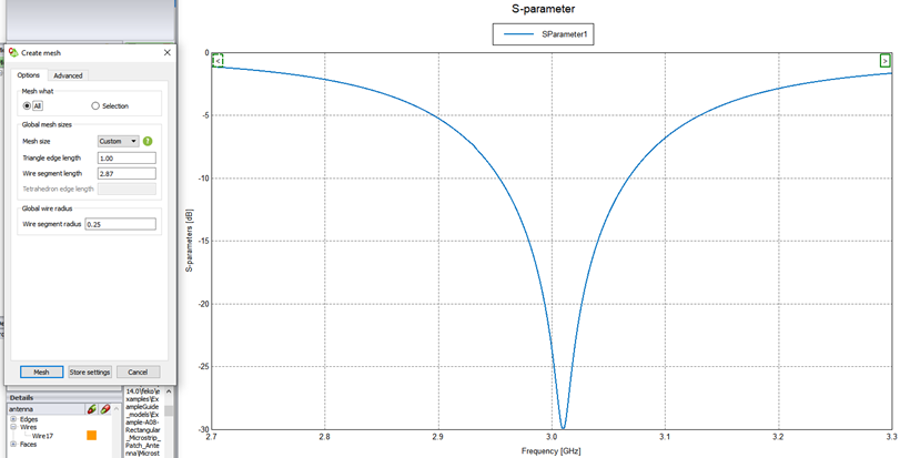
I'm having troubles getting example A.08-c (attached) from the Examples Guide to converge when measuring the S11. The resonant frequency seems to shift as I make my 'custom' mesh finer. 
the recommended mesh size in the example is 'standard' mesh which has a mesh size of approx. 4.9 mm, as I decrease the mesh size the results seem to be inconsistent.
I'm trying to find out the most appropriate mesh size while using a custom mesh. 


Standard Mesh: 
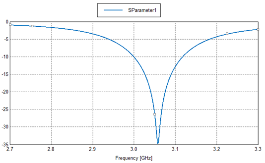
image.png.657de7f5c392cd4d42cb5f719a6cf953.png


Fine Mesh:
image.png.473eff2196bb1c814dffbeafd1e2b2bf.png


Custom mesh (4.9 mm): 


image.png.f617206e79176b75fb0c9cf9d2b89df2.png


Custom mesh (2 mm):


image.png.582e815a9f23f310dba9798f1def23a8.png


Custom mesh (1 mm):


image.png.0b5724c0bbedfd3711e6ece93bb9bc46.png


Unable to find an attachment - read this blog

Tagged:

Answers

  • Mel
    Mel Altair Community Member
    edited July 2019

    Hi Mraei


    The problem is the wire feed connecting to the triangles. The wire is becoming too thick compared to triangle sizes as you make the triangles smaller and smaller.


    You could consider using a cylinder meshed into triangles and the edge port to feed the patch.

  • mraei047
    mraei047 Altair Community Member
    edited July 2019

    Thanks Mel, I did create a model using a cylinder instead of a wire but I had a hard time trying to excite it properly and getting the appropriate result (i.e resonance). 

    I used a different model, also from the example guide (attached) which fed by a microstrip line feed rather than a wire feed. The idea was to isolate the problem by eliminating the wire feed altogether. This time the results improved, however, I still don't believe they are converging. 


    Standard Mesh: 


    image.png.2cc9b445371e6a18a753a2a72920d5cf.png


    Fine Mesh: 

    image.png.6fde77e95d14035ed1f1419435b27e97.png


    Custom Mesh 5 mm: 


    image.png.d048ea228e2352b31790798226d93c70.png


    Custom Mesh 3 mm:


    image.png.1e4fb2347f99d158329c3e4b6f04b68f.png


    Custom Mesh 1 mm:

    image.png.48b0e3c9e018836bff793fcf73d7ac0e.png 


    Unable to find an attachment - read this blog

  • Mel
    Mel Altair Community Member
    edited August 2019

    Mraei,


    The wire ports and edge ports still introduce discontinuities into the solution. Ideally one would want some sort of wave port. The FEM has a modal port but for this application it is impractical to construct.


    Accuracy/convergence can be improved further by keeping the feeding edge for the microstrip port and edge ports to be lam/30 or smaller. Also adding 'edge celling' by imprinting lines near the edges of the feed line should also improve accuracy.


    Attached an image of the idea for the construction and meshing.

    alternate_feed_and_edge_celling.png


    Also consider to plot the real and imaginary parts of the impedance rather than the input reflection coefficient. It might give a better idea of the convergence.