Composite modeling in HyperMesh

Imre.F
Imre.F Altair Community Member
edited October 2020 in Community Q&A

Dear forum members!


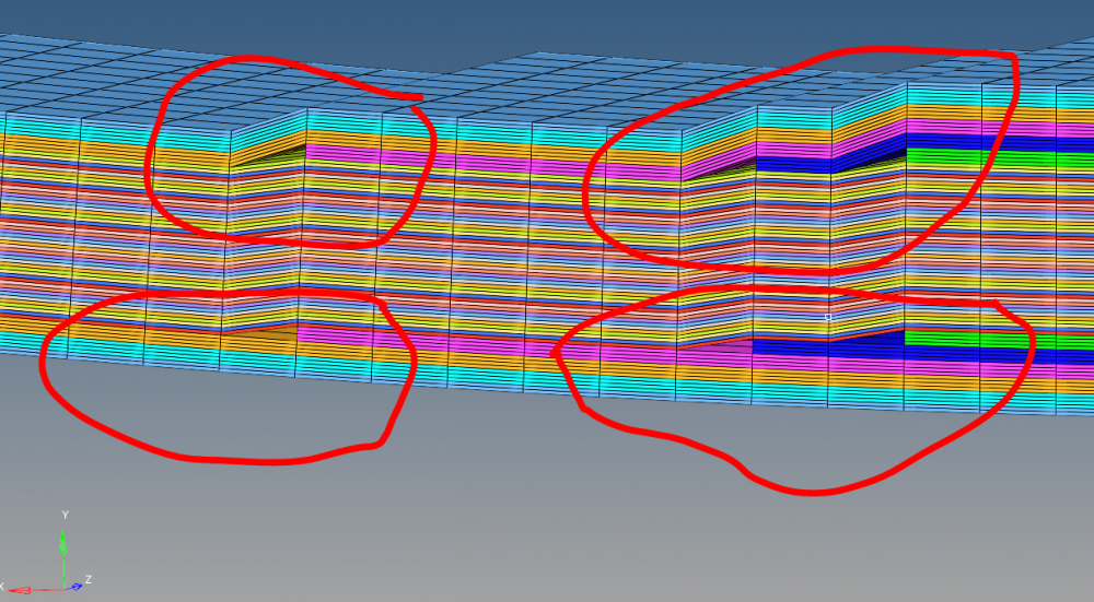
I am new member of Altair community and I am trying to model composite laminate. I created some plies with difference patches and the visualization of the different layers made me little anxious.


You can see the mentioned composite layers on the attached images. The plies are symmetric in the laminate nonetheless the 3D visualization of the composite showed differences between the upper and the lower side of the composite plate. I am afraid that this kind of modeling will lead poor results.

I tried to change the type of the laminate from stack to symmetric but the result was the same.


How can I model the composite properly if I want to 'mirror' the top half of the composite plate to the mid-plane?

Somewhere I read about sub-laminates but at first look seemed complicated. I would be happy if I could solve this modeling problem easier.


Thanks your answers in advance!


Have a nice day!

Imre.F

<?xml version="1.0" encoding="UTF-8"?>composite_01.PNG
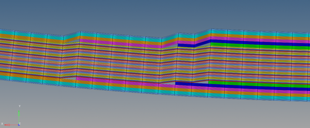
<?xml version="1.0" encoding="UTF-8"?>composite_02.PNG

Tagged:

Answers

  • tinh
    tinh Altair Community Member
    edited September 2019

    Adjust ZOFF of laminates?

  • Imre.F
    Imre.F Altair Community Member
    edited September 2019

    Hey tinh!


    It does not help. The result is the same even if I change Z0 options to Bottom/top/real (and I write in a z0 value). The visualization of the real and the bottom options is like each other's reflection.

  • QuyNguyenDai
    QuyNguyenDai Altair Community Member
    edited September 2019

    You say the plies are symmetric ? On the picture I do not feel that the plies are symmetrical.

    With symmetrical plies, you define only a half by using 'sym'. 

  • Simon Križnik
    Simon Križnik Altair Community Member
    edited September 2019

    Hi,


    on the PCOMPP card set Z0 OPTIONS to REAL and leave Z0 blank (no value). 

    Share the model if the issue persists.

  • tinh
    tinh Altair Community Member
    edited September 2019

    Hey tinh!


    It does not help. The result is the same even if I change Z0 options to Bottom/top/real (and I write in a z0 value). The visualization of the real and the bottom options is like each other's reflection.


    Vizualization is not important. If you set ZOFF solver will 'understand' and compute with the value. Sometimes hm visualizes problems.

  • Imre.F
    Imre.F Altair Community Member
    edited September 2019

    I share the file with you. You can see that the plies are symmetric (colour of the plies is the same in both side of the composite).


    I think the problem is that I created the plies on a surface and the laminate option 'lay up' these plies/patches on this surface. In this case the visualization shows the stack just right.

    However, the model is attached, if you have time please take a minute to look into it.


    Thanks your help, btw!

    Unable to find an attachment - read this blog

  • Simon Križnik
    Simon Križnik Altair Community Member
    edited September 2019

    Hi,


    with the setting Z0=blank, the plies will be arranged symmetrically, i.e. half the laminate thickness on both sides of the surface geometry (see image attached).

    Or have I misunderstood what you are trying to do?

    <?xml version="1.0" encoding="UTF-8"?>comp.jpg

    Unable to find an attachment - read this blog

  • Imre.F
    Imre.F Altair Community Member
    edited September 2019

    Hey Hyperman!


    Thanks for your effort, you understand me well.

    I was lame and did not leave the z0 offset blank, I left there a 0 mm value.


    Thanks again, you are the real hero, not superman. :)/emoticons/default_smile.png' srcset='/emoticons/smile@2x.png 2x' title=':)' width='20' />