Product = GENESIS
Lattice structures can be printed today using 3D printers. One question that arises is how to find the optimal dimensions of the lattice members. In this blog we want to address that question. As discussed in one of our previous blogs, “Fast Structural Analysis of Lattice Structures using GENESIS”, with the GENESIS software, standard solid elements (HEXA, PENTA, TETRA, etc.) can be used to simulate lattice structures. The software uses homogenized materials that can represent either a built-in lattice pattern or a user-supplied lattice pattern. This ability means that the lattice structures do not need to be explicitly modeled which makes the analysis of the structures very fast. To use a lattice pattern in a FEA simulation, the user only needs to select a lattice type, pick two characteristic dimensions: the lattice cell size and the lattice cross section dimension and optionally a coordinate system to orient the lattice cells. Lattice Types Currently, there are fourteen built-in lattice types in GENESIS: CUBIC1, BCC1, BCC2, DPYRA1, DPYRA2, HCOMB1, HCOMB2, HCOMB3, GYROID1, SCHWAP1, SCHWAD1, GYROID2, SCHWAP2 and SCHWAD2. The following figure shows the built-in lattice cell types:

Figure 1 – Built-in Lattice Cell Types in GENESIS Lattice Cross Section Dimension
GENESIS, currently, can optimize the cross-section dimension of any of the available lattice’s cells. In this blog, we will discuss how to optimize a lattice structure using one of the cell types. Example: How to Optimize a Lattice Structure To demonstrate the design of a lattice structure we will utilize the structure shown in Fig. 2. There are five load cases in this problem. In the first load case, vertical loads stretch the structures; in the second load case, lateral loads are applied from the right to the left; in the third load case, lateral loads are applied from the left to the right; in the fourth load case, loads are applied to compress horizontally the upper part of the structure. Finally, in the fifth load case, loads are applied to stretch horizontally the upper part of the structure. The loads are not shown here, but they are applied on the interior of the two circular holes in the top part of the structure. The bottom four circular holes are fixed so that they would not move under the applied loads. 
Figure 2 - Solid Model with Homogenized Properties
A lattice pattern consisting of 5x5x5 mm3 unit cell with the shape of double pyramid is selected from the pool of available shapes as the base design. The initial diameter of all the circular members of the cell can be any reasonable number consistent with the cell dimensions, in this problem we chose it as 2 mm. Fig. 3, below, shows the chosen cell.

Figure 3. Shape of the Selected Lattice Structure Cell: Double Pyramid Shape 1 To optimize this structure, we need 4 steps:
- Create the objective function. In this problem we will minimize the mass of the structure.
- Create the constraints. In this problem we will constraint the magnitude of the lateral displacements at the top of the structure in all load cases.
- Create a base design variable. The base design variable will start at 2.00 mm and will be restricted to be between 0.5 and 3.0 mm.
- Select the topometry region. The topometry region will be the elements in the red volume in Fig. 2
The previous steps are very easy to set up in Design Studio. Here, in Fig. 4, we will show part of the step number 4: 
Figure 4 – Data Generation for a Topometry Region
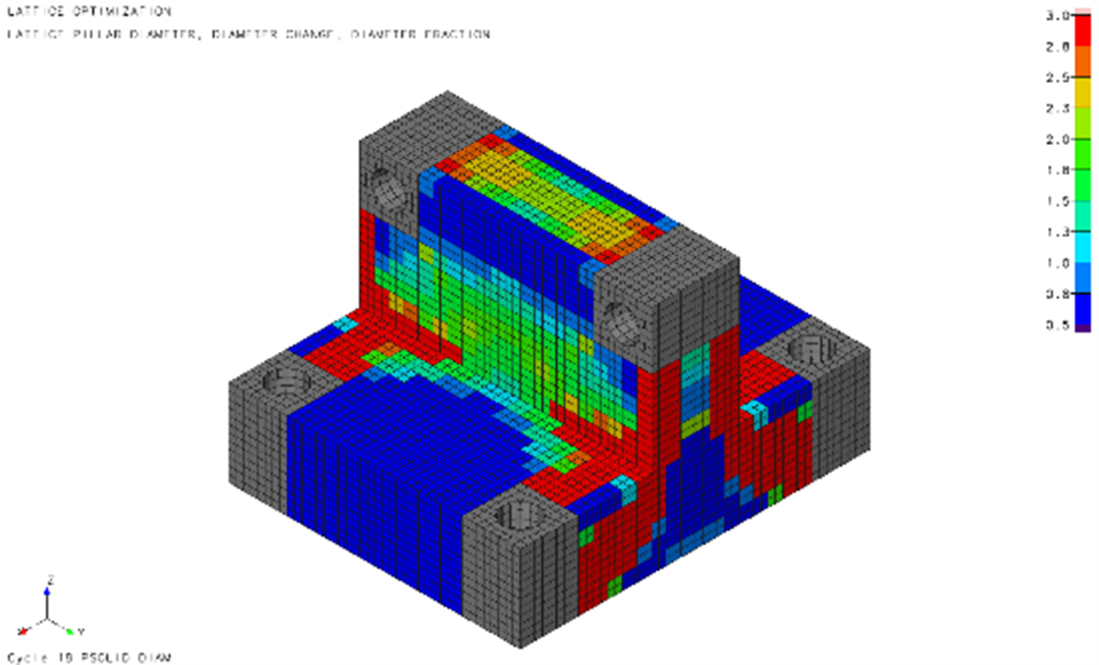
Once we complete the four steps above, we can run GENESIS and after few minutes we can load the topometry design results to visualize the results using Design Studio. Next, in Fig. 5, we show the thickness distribution on the solid mesh. The colors vary between 0.5 and 3.0 mm, which are the bounds set in the base design variable. 
Figure 5 – Thickness Distribution of lattice Dimension on the Solid Model with Homogenized Properties
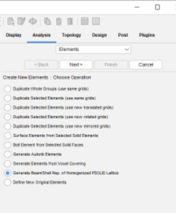
Once we complete the optimization, we can also use Design Studio to create a lattice structure model to visualize the results. To generate the lattice structure model, we just need to follow a few steps, which start with the following form:

Figure 6 – Data Generation to Generate a Lattice Structure
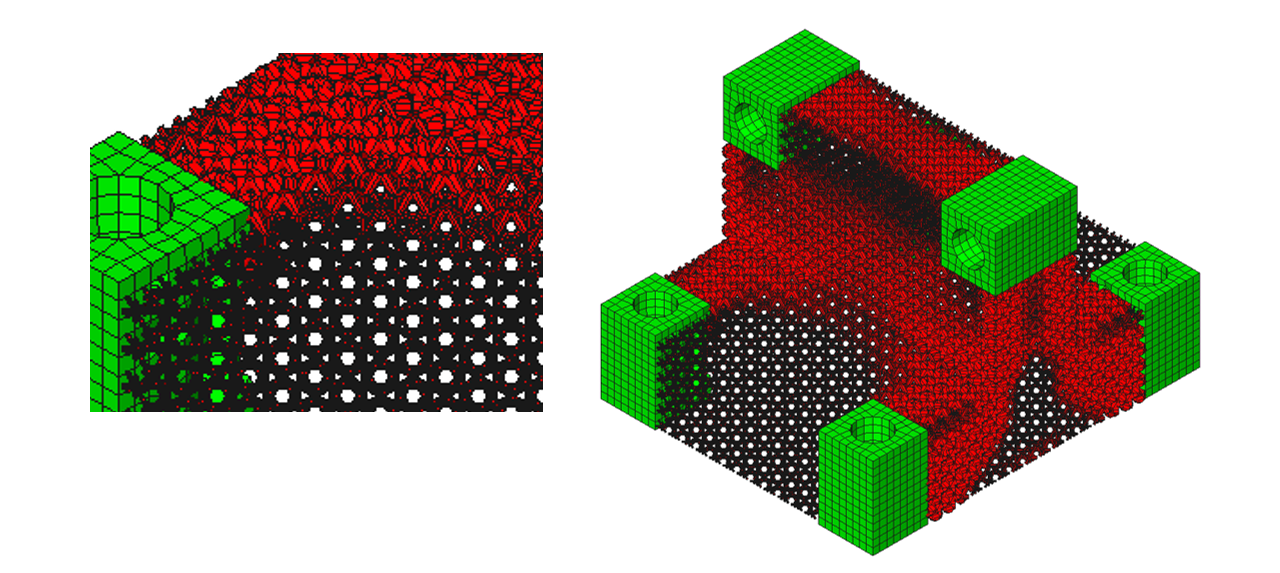
Fig. 7 shows the shape of the optimized lattice structure. In the figure, thinner members are very distinct from the thicker ones, so the figure clearly shows where more of the material of the lattices is needed and wherever less is needed.

Figure 7 - a) Enlarged Detail of the Lattice Structure (cell type DPYRA1) b) Final Design of the Lattice Structure
Summary The GENESIS software can be used to obtain optimal dimensions of lattice structures. In the example presented here, we used the homogenization method to get fast analysis and fast optimization results. 
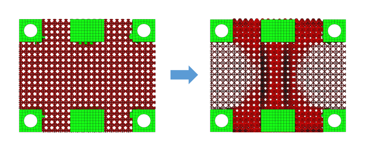
Figure 8 - a) Initial Design of the Lattice Structure and b) Final Design of the Lattice Structure (cell type DPYRA1)
Fig. 8 shows a top view of lattice designs. On the left, Fig. 8.a, the initial design is shown and all lattices have same dimension. On the right, Fig. 8.b, the final design is shown, there the thinnest members are 0.5 mm, while the thickest members are 3.0 mm. All the data needed to solve the problem for this problem was created using Design Studio and key steps of the process were shown in this blog. To learn more about this type of problem, users can study the Design Studio’s step-by-step example manual or contact us for more information. Details of examples similar to the one shown here can be found in the Design Studio for GENESIS examples manual. Check examples TMDSG015 and TMDSG016. If you currently do not have GENESIS and/or Design Studio, please leave a comment below.