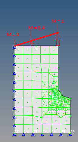
Is there a method to linearly distribute a moment on edges?
Hello, I want to apply a load to the edge of a symmetric model, starting with a moment of 0 on the symmetry edge node and increasing linearly to the outermost node of the (load-) edge (see picture).
How can a moment be distributed in this way?
Answers
-
you can accomplish that using the 'equation' option in 'moments' panel.
You define a reference system (or global, depending on your coordinates), and then create the moment distribution using this system and an equation like shown below. (x is your x-coordinate along the local system).
You just need to write the equation correcly so that the last value is 1.
Something like: (1/your_length)*x
0 -
Thank you Adriano, which .tcl code is corresponding to this?
If been working with *loadcreateonentity so far, but the docu does not provide me with more inside.
*loadcreateonentity
Creates a load (forces, temperature, moment, velocity, acceleration, or constraints) on nodes, fixed
points (surface vertices or weld points), surface edges, and surfaces.
Syntax
*loadcreateonentity geomtype markmask config type component[1-6]
Type
HyperMesh Tcl Modify Command
Proprietary Information of Altair Engineering
Altair HyperMesh 2020 Reference Guide
Scripts p.1274
Description
Creates a load (forces, temperature, moment, velocity, acceleration, or constraints) on nodes, fixed
points (surface vertices or weld points), surface edges, and surfaces.
Inputs
geomtype
Type of entity the load is applied on (e.g. SURFS).
markmask
The ID of a mark containing the entities that will bear the load.
config
The configuration of the load:
1 - Force
2 - Moment
3 - Constraint
5 - Temperature
6 - Flux
8 - Velocity
9 - Acceleration
type
The type assigned to the load (as defined on the 'load types' panel).
component[1-6])
Components of the load being applied.
When applying a force, the active components are 1, 2, and 3, which represent a force x, y, and
z-axis, respectively.
When applying a moment, the active components are also 1, 2, and 3, and represent the moment
about the x, y, and z-axis, respectively.
For constraints, all of the components are active unless they are set equal to -999999.0. All the
other components of the constraints are active in the respective directions.0 -
you're doing something that many people often skip, that is to go thorugh the documentation, which is great! /emoticons/default_smile.png' srcset='/emoticons/smile@2x.png 2x' title=':)' width='20' />
but in your particular case, concerning scripts, sometimes is easier to just perform the operation manually in HM first and take a look at the 'command.tcl' file created in documents folder.
look at the commands below:
*createmark nodes 1 a bunch of nodes......
*loadcreateonentity_function nodes 1 2 1 0 0 1 0 0 1 0 0 0 '3*x'
some of these arguments are the global system that i've selected and some of them are the direction (z 0 0 1)
Now looking at the help you whould be able to find more about this command.
0 -
Thank you very much, Adriano. I didn't know that there are commands that are not documented in the scripting reference manual.
0