Patch Antenna Simulation Issue
Hello
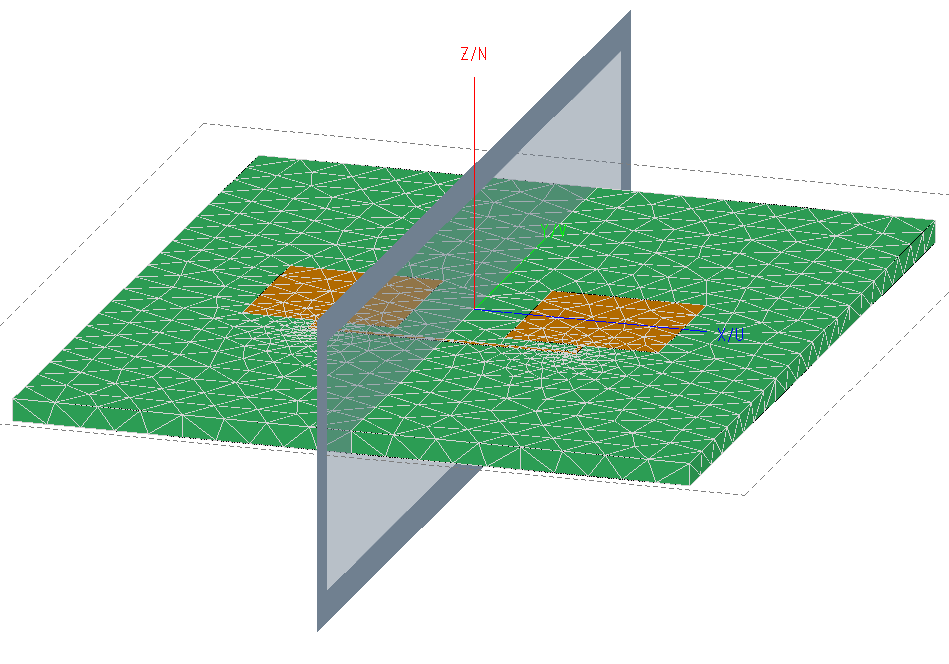
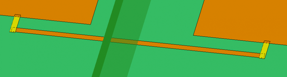
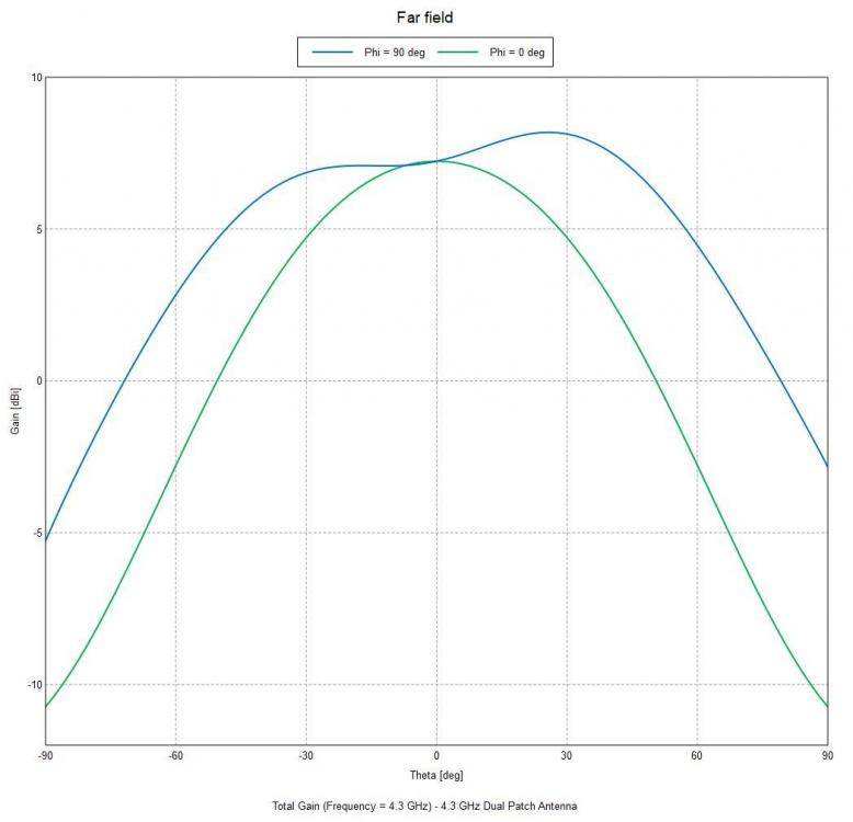
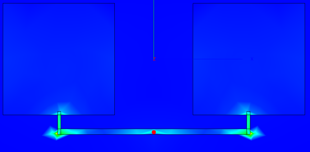
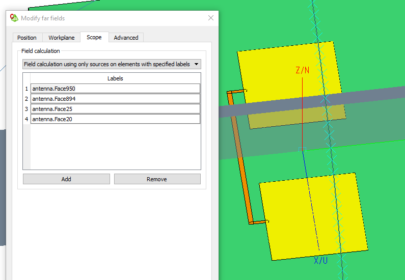
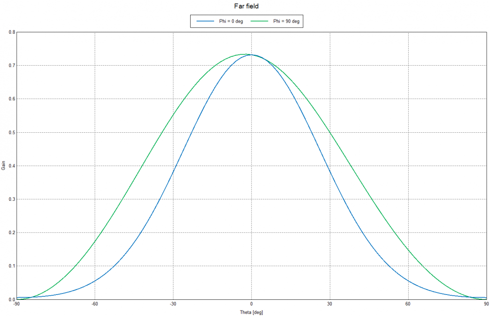
I am trying to simulate a patch antenna that consists from 2 patches and should work on 4.3 GHz center frequency. For some reasons The Y (V) antenna pattern cut is not symmetric. The X (U) cut is symmetric and VSWR value looks ok.
Attached the antenna design data.
I kindly request your assistance to find out the reason for this symmetry issue.
Thanks in advance.
Find more posts tagged with
Sorry.
Now all the files are attached.
Your support is highly appreciated.
Hi sem,
For 100% symmetric results, the mesh needs to be symmetric. Keep in mind that not the geometry but the mesh is solved (currents on edges between adjacent triangles). Plus, when applying symmetry planes in CADFEKO you will drastically decrease runtime/memory.
In your model a magnetic symmetry plane can be applied (after simplifying), see
Hi sem,
I'm not sure why you expect the ff_VN far field to be symmetric? The model is not symmetric to the VN plane, and as Johan Huysman already mentioned, the (strong) currents in the feed lines contribute to the far field radiation:
You may specify which faces contribute to a far field by using Scope in the far field diaogue. Here, only the patches are taken into acount:
Now the patterns are almost symmetric. Of course still the position of the feedlines disturbs.
Hello
I have solved the symmetry issues stated above and have proceed with the design. Now I want to round the 4 substrate corners by the radius of 6.35 mm to better simulate the antenna.
How can I do that?
I attach the latest design.
Your assistance is highly appreciated.
Thanks in advance.
Hi sem,
I would just add circular ellipses to the patches (!!! use snapping with ctrl + shift !!!) and then change face properties. The attached video shows how to do:
Hello
I have meant above that I want to round the substrate and not the patches. Nevertheless I have done it using CAD SW tool and then have imported it back (the substrate) to FEKO and redefined its parameters and it works.
Now I want to duplicate my antenna (have 2 identical antennas in same FEKO design) in order to calculate a coupling between them. Since the antenna substrate now is a primitive object, I have a difficulty to move it.
How can I solve this issue?
Thanks.
Hi sem
I don't see the model file attached. If you want others to take a look at the antenna design, please also your CADFEKO model file (.cfx).
Kind regards
Madelé