Node connectivity VS. contact surface (UnitCell Study)

Keonkim1991
Keonkim1991 Altair Community Member
edited October 2020 in Community Q&A

I'm currently working on a unit cell study (carbon fiber + matrix + additives). I thought it would be very easy to mesh it out and run my test, but I've been spending too much time in determining good quality of mesh. I have 3 components (3 different solids) that need to be meshed.


I was able to successfully tetra-mesh individual solids with curvature and proximity, but couldn't find the way to somehow connect them. 

I tried to re-mesh multiple times with 2D automesh to tetra mesh technique, translating surface meshes to another, assigning equivelent on the duplicated nodes, etc. But frankly, it's too time consuming to accomplish good quality mesh, and I can't spend more time in this part.


Later on I found the contact surface method preventing the penetration between parts by assigning slave and master BCs on shared surfaces (i.e. outter surface of carbon fiber and inner surface of matrix). Please give me some advice whether node connectivity can be replaced by assigning contact surface. My one concern is that later on I'll have to check the carbon fiber penetration in a reality scenario, and this method won't work for that due to the slave/matster bounded condition. If node connectivity must be properly done (which I assume..), please provide me some type of tutorials that present about connecting 'multiple solids'. I've went thru lot of meshing tutorials but only found the ones for single component/part or simple geometry setup that can be easily automeshed/translated/rotated..


Figure displays the carbon fiber (purple) and matrix (gray) nodes are not connected.
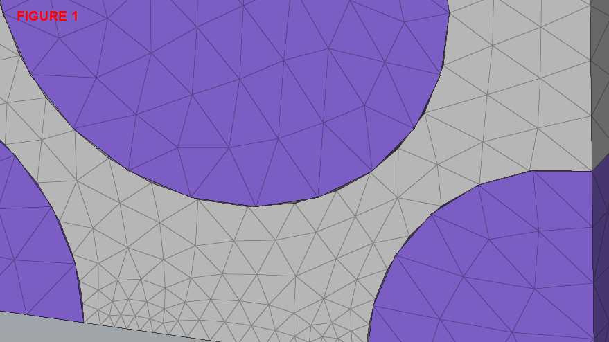
image.png.36e08b6c81ae1085f67bb3e942050605.png


Figure 2 displays the contact surface BCs applied on the shared surfaces of carbon fiber and matrix.
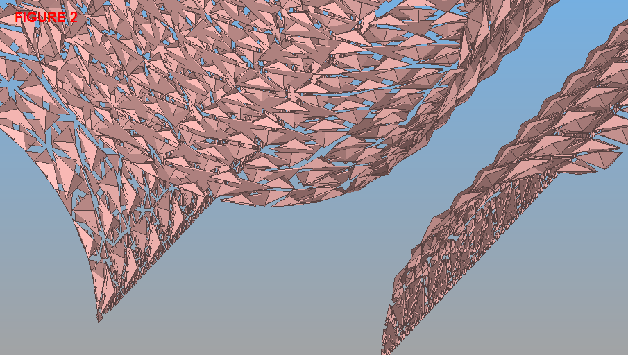
image.png.95d9bb16c38c638b4793675aba05527a.png


Please excuse that I am not allowed to upload the model..

Your help would be really appreciated.

Tagged:

Answers

  • Altair Forum User
    Altair Forum User
    Altair Employee
    edited July 2018

    Hi Keonkim1991,


    Please can you show your entire model. Did you try Equivalence option?

    <?xml version="1.0" encoding="UTF-8"?>image.thumb.png.c305595a3af9b71a9b38b3c214b3d140.png


    Thank you

  • Altair Forum User
    Altair Forum User
    Altair Employee
    edited July 2018

    Hi Keonkim1991,


    First mesh the grey component and then project those elements to the inner blue surface, and then perform volume tetra mesh. Since, you are meshing each component separately, there is no connectivity between the components. So, please try as i suggested.

    image.png.b12734d830192ef15f3b6e25122ff8d1.png 

    Thank you 

  • Keonkim1991
    Keonkim1991 Altair Community Member
    edited July 2018

    Hi Premanand, 


    Yes I've tried the equilvalent option, and I was only able to connect very few nodes due to the meshes from different solids are not referenced each other.


    Please excuse me I can't upload the model due to company's confidentiality.. What do you mean by projecting the grey elements to the inner blue surface? Can I somehow extend the grey mesh into the geometry of the blue circle? Please give me more details...

  • Keonkim1991
    Keonkim1991 Altair Community Member
    edited July 2018

    I'm currently trying an imprint option that I can select the source/destination. 

    I've tried source as the blue circles, destination as the grey, and remain the destination, also vice versa. But it's giving me an error of Input elements must be of the same order. What does this mean? And how can I proceed this method? Or is there any other more efficient ways?


    <?xml version="1.0" encoding="UTF-8"?>image.thumb.png.8fe2d09993a08d797286b67f619e2194.png


  • Keonkim1991
    Keonkim1991 Altair Community Member
    edited July 2018

    Can I please get some help here please

  • Altair Forum User
    Altair Forum User
    Altair Employee
    edited July 2018

    I'm currently trying an imprint option that I can select the source/destination. 

    I've tried source as the blue circles, destination as the grey, and remain the destination, also vice versa. But it's giving me an error of Input elements must be of the same order. What does this mean? And how can I proceed this method? Or is there any other more efficient ways?


    <?xml version="1.0" encoding="UTF-8"?>image.thumb.png.8fe2d09993a08d797286b67f619e2194.png


    Use Project option in Tools panel. Select the elements from grey area and project them to blue surface. And perform volume tetra mesh.


    I'm sorry for late reply, this is weekend and I'm not in office for two days. I'll will be in office on Monday.


    Thank you

  • Keonkim1991
    Keonkim1991 Altair Community Member
    edited July 2018

    Hi Premanand,

    You sir are the best. Thank you very much.

    I was able to create mesh on the circles both sides like below.


    <?xml version="1.0" encoding="UTF-8"?>image.thumb.png.34e68acf724b3f7e3928ef4cf1a5a79d.png


    And then I copied the inner cylinder part of the matrix, copy the elements on that surface and assign it to the carbon fiber as below.

    I made sure they share same nodes as well (In the end I made them equivalent). 

    <?xml version="1.0" encoding="UTF-8"?>image.thumb.png.f0942e259370cde516a705487feddaaf.png


    Later on I was able to assign the tetramesh on the part (masked view).

    <?xml version="1.0" encoding="UTF-8"?>image.thumb.png.fc8bff5668349371fd8ea1c30a0f6218.png


    So I believe I was able to connect the nodes from one solid (matrix) to another (carbon fiber).

    But for last clarification, all the unit cell study has to have the node connection between different solids? Is it always the case? Please help me understanding..


    Have a great weekend and hope to talk with you on Monday.

  • Keonkim1991
    Keonkim1991 Altair Community Member
    edited July 2018

    In addition, I ran a dummy analysis to study mesh convergence. As you can see below, significant changes in stress between elements from matrix to carbon fiber can be seen below (1.5 MPa to 240.4 MPa from blue to red element). Shouldn't it change smoothly? Not like this crazy changes. This is my initial run so mesh is real fine, so I don't believe it's due to element quality errors. Also, I made sure all the nodes were connected and all the duplicated nodes were assigned for equivalent. Not sure why it's like this?

    <?xml version="1.0" encoding="UTF-8"?>image.thumb.png.f3e33554d230255595170d54c87312c1.png


    My BCs are pretty simple: Top plane (RBE - compression load in -x axis on an independent node) and bottom plane (SPC constraints).

    Please help me understanding this drastic stress transfer.

  • Altair Forum User
    Altair Forum User
    Altair Employee
    edited July 2018

    all the unit cell study has to have the node connection between different solids? Is it always the case? Please help me understanding..

    Please refer this doc. to understand this. I think node to node connection is must for unit cell study. (I don't know much about it, sorry)

    https://www.gidhome.com/wordpress/wp-content/uploads/p204.pdf


    My BCs are pretty simple: Top plane (RBE - compression load in -x axis on an independent node) and bottom plane (SPC constraints).

    Please help me understanding this drastic stress transfer.

    Please can you show your BC's with snapshots. Also, can you share more details about properties and material data's assigned to the model.


    Thank you


  • Keonkim1991
    Keonkim1991 Altair Community Member
    edited July 2018

    Good morning Premanand,


    Thank you for your reference for the node connectivity. 

    I used PSOLID for all properties as the model was 3d-tetrameshed.

    For materials, Carbon Fiber: E = 231000 MPa, NU = 0.2, RHO = 1.76e-009 & Epoxy: E = 3425 MPa, NU: 0.32, RHO: 1.25e-009.


    But please note that, due to this study includes dummy load for only convergence study, the geometry scale was left as default (milimeter) when it should be micrometer in reality scenario. So stress result values itself are not correct, but this is to only investigate the stress transfer between elements from different solids.


    And to help you understand more details, below is my BCs.


    1. Top plane (RBE - compression load in -x axis on an independent node) 

    2. Bottom plane (SPC constraints - all nodes on the bottom plane)


    image.png.09f1eb47e69980ec75c895820f3a2447.pngimage.png.4533ecc14552db96928928fa07befdba.png


    Thank you for your help.

  • Altair Forum User
    Altair Forum User
    Altair Employee
    edited July 2018

    Hi Keonkim1991,


    Stresses value depends on the material properties. Carbon fiber is more stiffer than the matrix (E-Fiber > > E-Matrix). Hence you are getting more stress on the fiber than on the matrix (young's modulus is directly proportional to stress).


    Thank you

  • Keonkim1991
    Keonkim1991 Altair Community Member
    edited July 2018

    I found out that my BCs are wrong for unit cell compression. With this BCs below, the high stress in the corner of cube was eliminated and the structure uniformly deformed as I allowed free translation on the side edges.


    Thank you for your help.

    UnitCell.png.0d0dc181c677443143c769da5b3b27a6.png