Aerospace Tool Issue
Hi,
I was just trying out Aerospace -> Beams -> Beams from Lines function in HM.
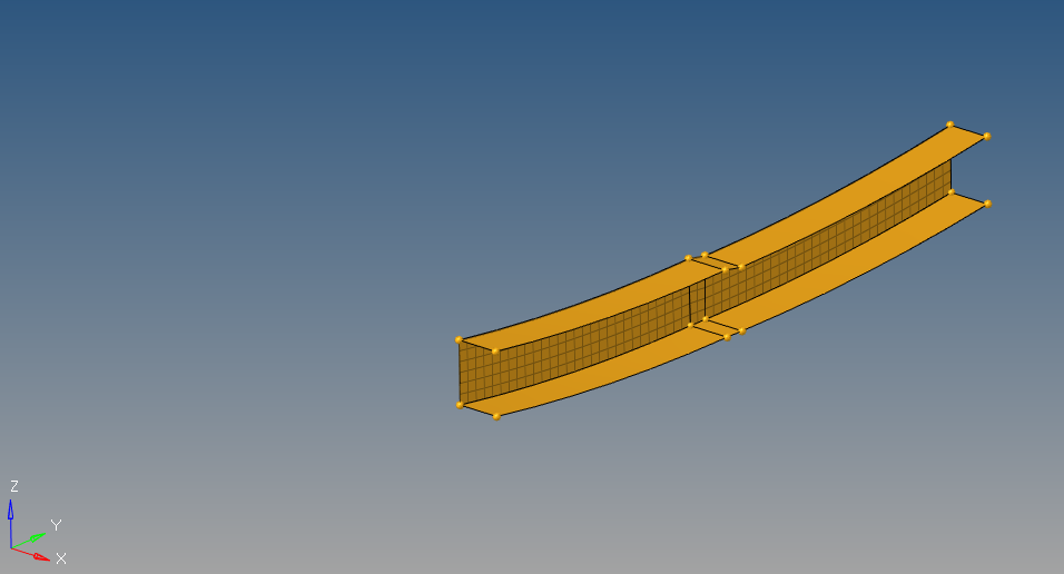
The part is a curved C-Channel which has a slight joggle in one of its flange. I wish to represent the flanges using CBAR/CBEAM elements while the web will be represented by CQUAD elements. Like the tutorials mentioned, I first meshed the web using CQUAD elements. Since my beam is curved, I created a cylindrical coord as well.
I populated the selection window per my understanding based on a HW 14 Aerospace webinar and as can be seen below, the results are not what I expected. The picture below shows me selecting just 1 line but I did select lines representing the top & bottom flanges in my previous attempt.
<?xml version="1.0" encoding="UTF-8"?>
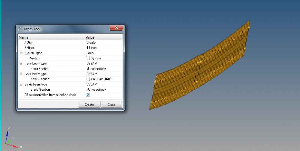
Where am I going wrong? Hoping to get a hang on this function so that I can reduce the time on creating beam elements manually.
Answers
-
Altair Forum User said:
Hi,
I was just trying out Aerospace -> Beams -> Beams from Lines function in HM.
The part is a curved C-Channel which has a slight joggle in one of its flange. I wish to represent the flanges using CBAR/CBEAM elements while the web will be represented by CQUAD elements. Like the tutorials mentioned, I first meshed the web using CQUAD elements. Since my beam is curved, I created a cylindrical coord as well.
My question: why you choose different modelization for flange & web? How do you do to 'link' between them?
0 -
Altair Forum User said:
Hi,
I was just trying out Aerospace -> Beams -> Beams from Lines function in HM.
The part is a curved C-Channel which has a slight joggle in one of its flange. I wish to represent the flanges using CBAR/CBEAM elements while the web will be represented by CQUAD elements. Like the tutorials mentioned, I first meshed the web using CQUAD elements. Since my beam is curved, I created a cylindrical coord as well.
<?xml version="1.0" encoding="UTF-8"?>
I populated the selection window per my understanding based on a HW 14 Aerospace webinar and as can be seen below, the results are not what I expected. The picture below shows me selecting just 1 line but I did select lines representing the top & bottom flanges in my previous attempt.
<?xml version="1.0" encoding="UTF-8"?>
Where am I going wrong? Hoping to get a hang on this function so that I can reduce the time on creating beam elements manually.
Hi,
Can you point me to the webinar your talking about?
0 -
Prakash,
This is the webinar: http://web2.altairhyperworks.com/hw14-model-build-webinar
Also, both in the webinar & in the tutorial, they chose an aircraft fuselage to demonstrate tool functionality. I am assuming that tool can work for applications other for typical structures like fuselage only!
Q.Nguyen-Dai, one of the ways to typically represent aircraft structures is to model flanges using CROD or CBEAM/CBAR elements & web by CQUAD elements. This type of rep is used in GFEM models and are typically used to calculate internal loads in various structures before doing a Detailed FEM for stressing purposes. I don't understand what you mean by linking. If you taking about connectivity, the 1D elements will be created along the edges of 2D elements. I've attached a picture of such representation of a stiffened panel.
0 -
Altair Forum User said:
Hi,
I was just trying out Aerospace -> Beams -> Beams from Lines function in HM.
The part is a curved C-Channel which has a slight joggle in one of its flange. I wish to represent the flanges using CBAR/CBEAM elements while the web will be represented by CQUAD elements. Like the tutorials mentioned, I first meshed the web using CQUAD elements. Since my beam is curved, I created a cylindrical coord as well.
I populated the selection window per my understanding based on a HW 14 Aerospace webinar and as can be seen below, the results are not what I expected. The picture below shows me selecting just 1 line but I did select lines representing the top & bottom flanges in my previous attempt.
<?xml version="1.0" encoding="UTF-8"?>
Where am I going wrong? Hoping to get a hang on this function so that I can reduce the time on creating beam elements manually.
I think you have some issue with flange part:
- Check section orientation of CBEAM
- Maybe you have to play with 'offset' to define C-Channel correctly. Without section offset, you model becomes T-Channel.
0 -
In HM help, it says y-axis of section is aligned with shell normals, so please try swapping DIM1 and DIM2 value of bar-section
0 -
Can you try with a different orientation?
0 -
OK. I will try changing the DIM1 & DIM2. Thanks Tinh.
0 -
Tinh & others, it kinda worked when I swapped Dim1 & Dim2 dimensions. The tool set the offset on the wrong side of the flange but I reckon, it can be updated manually or I just need to adjust shell orientation.
0