How to add pressure on the cylindrical solid element?
Hello.
I am trying add a pressure force on the inside of the cylindrical elements.
According to the topic as follows,
I extracted the inside of the solid element and add a pressure on it.
However, the result showed that there is no displacement or stress caused by inner pressure.
1. Is there any further setting to link solid element and extracted element ?
2. The property of '^faces' is blank. is it ok?
3. In HyperView, the extracted elements (named ^faces automatically) is disappeared. Is this right?
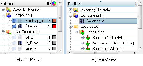
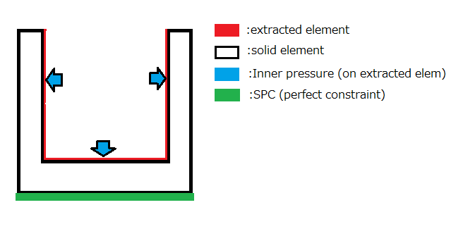
Following is model (half of cylinder), load and constraint setting.
Thank you for your answer.
P.S about question no.2, I added the property of solid element to the extracted component, but the result did not change.
Answers
-
Note: about question no.2, I added the property of solid element to the extracted component, but the result did not change.
0 -
For face you can provide negligible thickness say .001 mm.Could you let us the solver you are using at your end for run?
If it is Optistruct then please share .fem file.
0 -
Any component name which starts with '^' will be ignored/not exported.
Rename the component and assign a Shell property (as the extracted elements are shell elements) and assign property and material.
0 -
Dear Mr. Rahul,
Thank you for your assistance.
I am using Optistruct so I sent .fem file (and also .hm, .h3d file for your information.) to your dropbox.
Best regards,
0 -
Just made some changes in your model.For solid element use PSOLID card.
In your fem file you have created Inner pressure load collector but no pressure was applied on elements.Latest version allows to pick face of solid element.Try these changes it should work.PFA updated file for your reference.
0 -
Dear Mr.Rahul and Mr. Prakash.
Thank you for your advice.
Calculation was finished properly by addring PSHELL property and material to extracted element.
To Mr Rahul,
Thank you for your update. it worked.
Picking face of solid element is available only with HyperWorks 14 ? I am using HW 13.
Best regards,
0 -
-
Hello.
I did the analysis according to the above method.
I have some questions.
1. The analytical value of tensile stress and its distribution of the solid elements are close to the theoretical value.
However, the tensile stress that of at the shell element are bit different from the theoretical value, and its distribution is also different from theory.
( Please refer to the following picture.(these 2 shows the stress of YY direction in grobal coordinate system) )
Can I ignore (exclude) the stress and its distributions of the shell element because it is just a 'dummy' element ?
If I cannot, is any constraints or settings needed ?
<?xml version="1.0" encoding="UTF-8"?><?xml version="1.0" encoding="UTF-8"?>
Upper: Stress value and distribution at solid element
Lower: Stress value and its distribution at shell element (inside of cylinder)
Theoretical stress value: 78 MPa
Analytical stress value(without shell): 72MPa
Analytical stress value(with shell): 91MPa
2. Is this the only way to add the pressure on the solid element ?
(Createing dummy shell element on the solid element, and add the pressure on the them)
Red face: Shell element extracted from Solid element
Blue arrow: Inner pressure
Brown element: solid element
0 -
If you have access to latest version then try to apply pressure directly on solid elements & check.
0 -
Sorry but I only have a HyperMesh 13.
and additionaly, the second screenshot was wrong (The whole inside of cylinder is red) because it was just the component color, not the contour of stress distribution.
the contour of shell element shows similar distribution that the solid element shows.
I am sorry for the confusion. The screenshot has been revised.
0