Hello everybody.
To set up models efficiently and to investigate different seam weld representations, I try to put together some scripts or custom weld realizations. In the end, I want to create multiple short seam welds in a structure.
Currently I am strugling to find the right tools, commands and hypermesh functions to effectively realize those seam welds with little to no user input. Manually, I am able to create the realizations, but even though I can read out the comand.tcl, there is a lot of manual selection necessary and I do not know how to automate the process with the tools I have.
I quickly describe my ideas and I hope to get new ideas and suggestions, how to achive a good process of creating those welds.
Current situation:
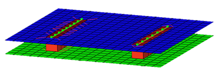
A very good function of course is the connector browser. A simple seam weld with solid hexa elements is quick and easy and I use this as a starting point to connect two sheets (shell meshes). Speaking in terms of the four-stage-process, mentioned in the user guide, I want to establish a seam weld using the 'Mesh dependent – adjust mesh – quad transition - imprint' process. Here I do not really know, how to create a seam weld using hexa elements and adjust the mesh accordingly, using quad transitions. But there are more aspects necessary:
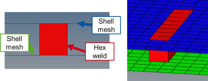
- solid hexa elements, connecting two shell meshes
- shell meshes adjusted to hexa elements (hole in shell mesh, where the hexa elements are located)
- fill hole in shell meshes with shell element row, which are in a separate component
- nodes of shell meshes and shell element rows should be at the same coordinates, but do not be identical. Shell meshes and shell element rows should use separate sets of nodes.
- between shell meshes and shell element rows, I want to create cohesive shell elements (here: quad shell element with zero length in one direction; node 1&3 and 2&4 have the same coordinates at the beginning of the analysis)
- solid hexa elements and shell meshes should also not share any nodes, but have nodes at the same coordinates
Has anyone good ideas on how to achive this kind of representation?
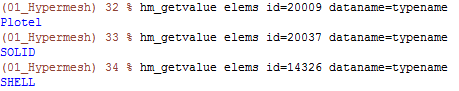
At the moment I am strugling with very fundamental stuff. For example I try to create shell elements from the solid elements to get those two rows of shell elements, that eventually fill the holes in the two shell meshes. Those rows of shell meshes, I could use to imprint in the shell meshes and to get my set of nodes, to create the cohesive shells.
Update 1:
I played a bit with custom fe_configs for realization types. It looks promising, but there are two main problems:
1. When I create a custom realization type, which is totally equal to hexa adhesive (see below), I have no possibility to enter the width of the weld.
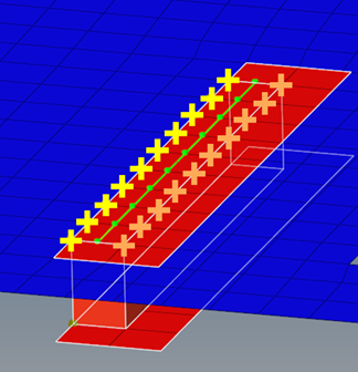
2. When I use 'Mesh dependent – adjust mesh – quad transition-skip imprint', only two rows of quad elements are created (see picture, quads in red). This leads to the weird problem, where some nodes are shared between solid and (red) shell elements (orange crosses) and some nodes are douplicated and not shared (yellow crosses)
CFG dyna 106 hexa (adhesive - shell gap) *filter seam *style continuous 2 *head *body 0 hex8 1 1 *post prop_dyna_matnum_seamarea.tcl