Non-Linear Static Analysis
Hi Everyone,
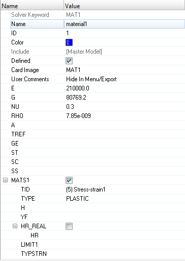
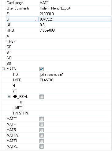
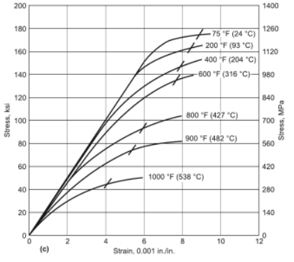
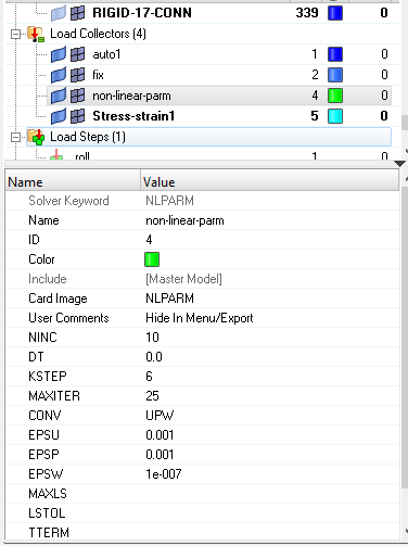
I was performing on my model through creating Stress-Strain curve and putting data values as per the curve given below. I have used NLPARM in Load Step.
The error it is showing is quoted as :
'The plastic material data specified on the TABLES1 bulk data entry ID=5
is invalid. The slope after the initial yield point is not less than the
Young's modulus. ( 1.468927e+005 >= 1.550543e+005 ) at the segment 2. '
I got, that the slope after the initial yield point should be less than the young modulus. So, I have ensure that very carefully in my curve but also it is showing the same error.
Kindly clear my doubt as if I am doing something wrong.
Thank you for reading and for answering.
Enclosure: In the curve I have selected the first curve among all the curves.
Answers
-
Hi,
can you show the stress-strain curve (TABLES1 bulk data entry ID=5)? The error states the issue is at the segment 2.
0 -
0
-
Now, the error is showing-
' *** ERROR # 1583 ***
for material id = 1 referenced from element id = 1.
MATS1 is presently not supported for second order shells (CQUAD8 and CTRIA6). 'But, according to my study MATS1 can be used for 2D SHELL elements.
0 -
It looks like the slope of the 2nd segment is steeper than first, which is not allowed. Please share the table data, because it is hard to estimate based on the curve you shared.
From Optistruct help:
If TID is given, TABLES1 or TABLEG entries (Xi,Yi) of stress-strain data ( εε x,Yx) must conform to the following rules:
If TYPE=PLASTIC, the curve must be defined in the first quadrant. The data points must be in ascending order. If the table is defined in terms of total strain (TYPSTRN=0), the first point must be at the origin (X1=0, Y1=0) and the second point (X2, Y2) must be at the initial yield point (Y1) specified on the MATS1 entry. The slope of the line joining the origin to the yield stress must be equal to the value of E. If the table is defined in terms of plastic strain (TYPSTRN=1), the first point (X1, Y1), corresponding to yield point (Y1), must be at X1=0. TID may reference a TABLEST entry. In this case, the above rules apply to all TABLES1 tables pointed to by TABLEST.
If TYPE=NLELAST, the full stress-strain curve may be defined in the first and third quadrants to accommodate different uniaxial compression data. If the curve is defined only in the first quadrant, then the curve must start at the origin (X1=0.0, Y1=0.0).
For analysis where small deformations are assumed, there should be little or no difference between the true stress-strain curve and the engineering stress-strain curve, so either of them may be used in the TABLES1 definition. For analyses where small deformations are not assumed, the true stress-strain curve should be used.
If the deformations go past the values defined in the table, the curve is extrapolated linearly.
MATS1 is not supported in conjunction with second order shell elements (CTRIA6 and CQUAD8). MATS1 is also currently not supported with 1D elements.
0 -
Thankyou for the reply,
So, for the Non-Linear Static Analysis where I want to give the stress-strain curve for the material, I have to perform in Radioss User profile ?
My structure composed of 2D Elements only.
0 -
Glad to help.
Non-Linear Static Analysis can be done in Optistruct using non-linear material (stress-strain curve). Just make sure to follow instructions from Optistruct help. Share your model if you need help with debugging.
Radioss explicit solver is more computationally efficient than Optistruct implicit solver for highly non-linear models with geometric, material and contact non-linearities.
0 -
-
PSHELL is shell element property and is supported by MATS1.
MATS1 is supported for first order shell elements (CQUAD4 and CTRIA3), but not second order shell elements (CQUAD8 and CTRIA6). You can switch between first and second order elements with 2D>order change
The following free ebooks are recommended:
Practical Aspects of Finite Element SimulationIntroduction to Nonlinear Finite Element Analysis using OptiStruct
0 -
Is there is a way to reconnect my rigid elements as I have changed my element order from 2 to 1 degree. But, my connection were earlier connected at mid side nodes. So, is there's a way to reconnect again those rigid elements or I have to create it again ??
The BLUE Marker showing midsize nodes which now is in valid as the the order is change to 1 degree
I have about approx 500 RBE2 Elements as shown below. So, is there's a way to reconnect it.
0 -
You should use 1D>connectors panel to automatically create connections.
Refer to tutorial HM3400: Creating Connectors for more details.
0