Weird phase illustration with FEKO

Haj Hassan
Haj Hassan Altair Community Member
edited October 2020 in Community Q&A

Hello,

we are currently working on metasurfaces to generate OAM waves or vortex waves.

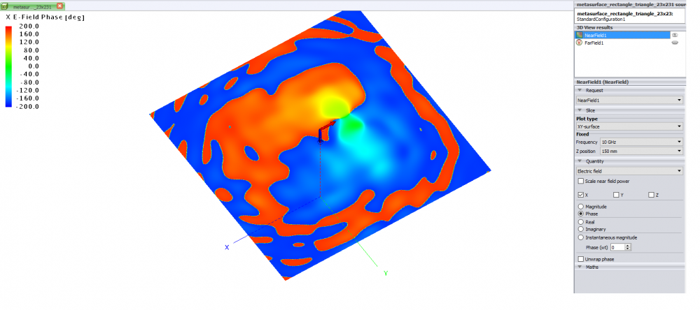
We are getting the correct radiation pattern, but some how we are getting the wrong phase.

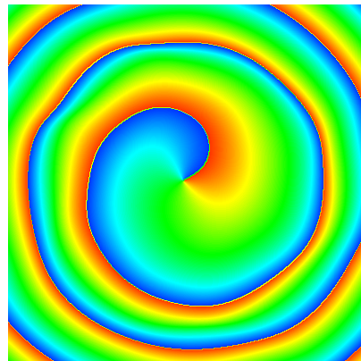
It should look like the picture of correct phase.

Is there anything i should pay attention to it in FEKO?


Thanks in Advance.

Best Regards

M. Haj Hassan


<?xml version="1.0" encoding="UTF-8"?>weird_phase.png
<?xml version="1.0" encoding="UTF-8"?>correct_phase.png

Unable to find an attachment - read this blog

Tagged:

Answers

  • Mel
    Mel Altair Community Member
    edited August 2020

    You may need to set the near field request to compute only the scattered part (to exclude the source contribution).


    Secondly, is the 0.1 mm gap between the large rectangles below intended? If the gap is correct, the meshing on the metallic edges on both sides of the gap should be roughly similar to the gap width, maybe try 0.3 to 0.5 mm.

    image.png

  • Haj Hassan
    Haj Hassan Altair Community Member
    edited August 2020

    Hello,

    thank you for your quick answer.

    How can i set only the scattered part?

    Shall i only choose the patches or everything (patches, with ground and substrate).

    Thanks in Advance.


    Best regards

    Haj Hassan

  • Mel
    Mel Altair Community Member
    edited August 2020

    Enable the scattered part on the Advanced tab of the near field request in CADFEKO. 

    image.png

  • Haj Hassan
    Haj Hassan Altair Community Member
    edited August 2020

    Hello,

    thank you very much.

    it is working.


    Best regatds

    Haj Hassan