Connect mesh of two components

Beginner93
Beginner93 Altair Community Member
edited October 2020 in Community Q&A

Good evening to everyone,


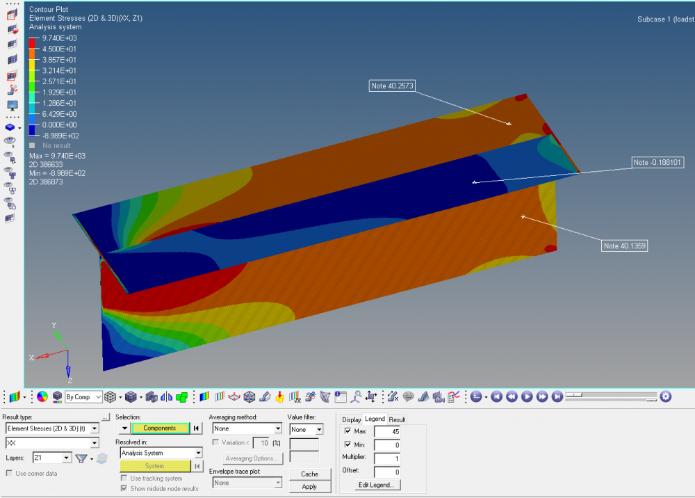
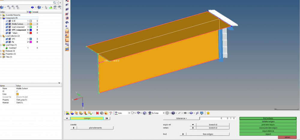
i´ve meshed a Model made out of three components. As you can see, i fixed the nodes between the components with the equivalence funktion. But on one side the components seem not to be fixed the right way. There is only on force in x direction. So the stress in xx in the whole component should be the constant. The analytical result is 40.336 MPa and on two of the three sides it´s right.

<?xml version="1.0" encoding="UTF-8"?>image.thumb.png.a5dbdf1e8aae9c77d075ac3eced45544.png
<?xml version="1.0" encoding="UTF-8"?>image.thumb.png.380743b44caf52961a53b1cd4bcfc40b.png


I´ve build the model a few times and get always the same problem. So if anyone could help me, i would be really greatful.


Thanks and greetings from Beginner.

Tagged:

Answers

  • Altair Forum User
    Altair Forum User
    Altair Employee
    edited May 2018

    Hi,


    Try combining both the surfaces using unsplit option or use extend option if your model is not connected properly. You would see a yellow line if they are connected.


    Thank you

  • Altair Forum User
    Altair Forum User
    Altair Employee
    edited May 2018

    Hello @Beginner93,

    Greetings!!!


    It would be more helpful, if you could share the mesh picture of your model, with close look near the connection.


    Also, in edges option, select for find edges - as sometimes, due to low tolerance value provided- set by user, may not equivalence all nodes.


    If you have free edges(SHift + F3), increase tolerance value and equivalence or manually connect the nodes with replace option (F3).


    Let us know, if you get desired results from analysis.

    <?xml version="1.0" encoding="UTF-8"?>image.thumb.png.0e030e45096e73fb0e6091f207ff367b.png


    Thanks & Warm Regards,

    Akshay S.Patil

  • Beginner93
    Beginner93 Altair Community Member
    edited November 2020

    Hi,


    thanks for your hint, but i´ve already tried everything. But always i´ve got the same result. I´ve increased the tolerance up to 0.200 because my mesh size is 0.250. But nothing changed.


    Maybe there is a problem with the model, but i can´t find anything. If someone can have a short look, i would be very grateful. 


    Greetings and thanks a lot,

    Beginner93


    Unable to find an attachment - read this blog

  • QuyNguyenDai
    QuyNguyenDai Altair Community Member
    edited May 2018

    You applied the force at ONLY ONE node! You can not get constant stress on all component.

    Do you know 'principle Saint Venant' of 'Strength of Materials' course?

    To test: make your beam 10x longer

  • Beginner93
    Beginner93 Altair Community Member
    edited May 2018

    @Q.Nguyen-Dai thanks for your help, i know that it couldn´t be the same stress on the whole cross-section with just a single force. But at the beginning and the end of the midsurface-beam i´ve made a slim component with a very high e-module, so the load is distributed on the whole beam. And only the area around x=0 is interesting for me. In this area in the results from two of the three stanchions are pretty good. But in one, as you can see in the picture, is nearly no stress. I don´t know how i can fix this, i tried all the good hints i´ve already got here. Don´t know if i´m just unable or if it isn´t possible the way i´d built the model.

  • Altair Forum User
    Altair Forum User
    Altair Employee
    edited May 2018

    Hi,


    Try creating separate system for your model, make sure X-Co-ordinate is in the loading direction. Change the Resolved in Field to > user system, with the system selector active select the newly created system as shown below. Then check the results.

    image.png.1ac4ad0ce94edea9d3008d61c70615a2.png

    Thank you

  • Altair Forum User
    Altair Forum User
    Altair Employee
    edited May 2018

    Beginner93,


    You have inadvertently created elements around the edge of the top flange on one side, e.g search for element 392903.


    Pete

  • Beginner93
    Beginner93 Altair Community Member
    edited May 2018

    @ellison thanks for your help. I already thought the same, so i meshed each surf one by one or meshed all together. But there is allways the same result. I really don´t know where is the problem. Is it the mesh or the model or anything else, i really don´t know....


    Thank you

  • Altair Forum User
    Altair Forum User
    Altair Employee
    edited May 2018

    Hi,


    Try creating separate system for your model, make sure X-Co-ordinate is in the loading direction. Change the Resolved in Field to > user system, with the system selector active select the newly created system as shown below. Then check the results.

    <?xml version="1.0" encoding="UTF-8"?>image.png.1ac4ad0ce94edea9d3008d61c70615a2.png

    Thank you

    Beginner93, try this. It works.


    Thank you

  • Mario_21478
    Mario_21478 Altair Community Member
    edited May 2018

    Hello,


    Premanand Suryavanshi is right with his help, here is a short explanation.


    If you are plotting X-component stresses in analysis system, then the stresses are orientated on the local element coordinate system.

    The X- direction of the top plate doesn't show all in the same direction. You can check it with Hypermesh->Tools->Orientation Review. See attached picture.


    You can either reorient the elements, or use the proposed tensor transformation by the 'Resolved in:' shown in upper picture.

    You can take global direction, or define a user system, or define projection rules.


    Best Regards,

    Mario


    <?xml version="1.0" encoding="UTF-8"?>image.thumb.png.356c5a6e1d3e644b772e00717076d818.png


  • Altair Forum User
    Altair Forum User
    Altair Employee
    edited June 2020

    hai everyone

    I am having a query that can we replace single component with two components in hyper mesh?