Multi-Static Kinematic Model of Magnets Error

rorythornton
rorythornton Altair Community Member
edited October 2020 in Community Q&A

Hello


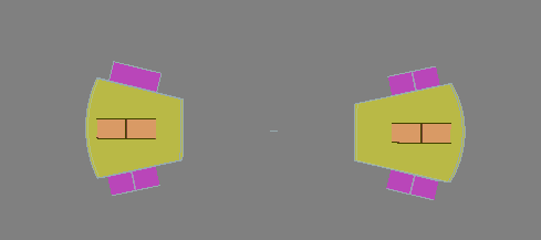
I am new to Altair Flux and I am trying to plot a torque-deflection curve for the following permanent disc magnet arrangement:


(Note: Infinite box is hidden)
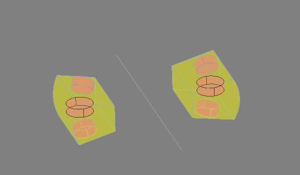
image.png.09a15deac45fdfb5b02817a7a483ce20.png        image.png.dcee712fa4fdfdb69e6cb7b71170c8fa.png


Where:

-The two magnets inside the yellow boxes rotate about the centreline shown in the LHS screenshot above

-The yellow boxes are the mobile air regions that the two magnets move through

-The four magnets outside of these regions are fixed and interact with the rotating ones to generate a torque


I have used the rotating motion tutorial shown below to help set this simulation up (adjusting it as best as I can for the model differences):
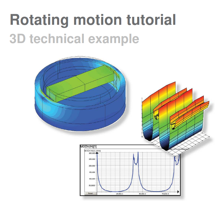
image.png.868df07ad8ed1129d62b6e6e0c054be8.png

I followed this as closely as I could when I set up my model


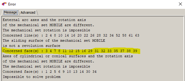
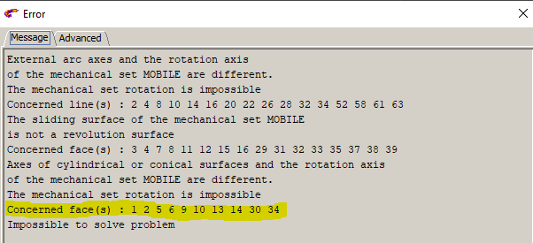
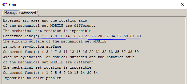
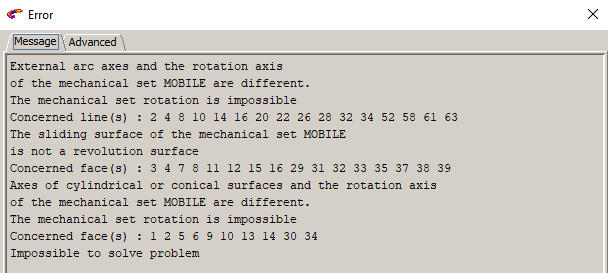
When I try to solve the simulation, I get the following error:

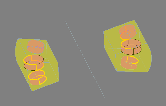
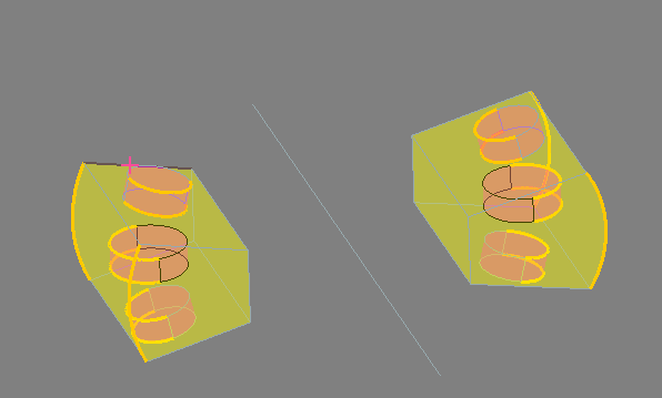
(Note: For each line that reference geometrical features, I have highlighted them in the model on the RHS)
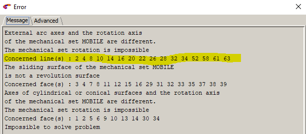
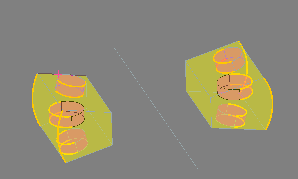
 

image.png.910cdca2d94b3f7045e04fcb365fc44d.pngimage.png.7690d6ce44d5d0e059a4ff4ac92515ec.png 


image.png.370981151907d2b56bea2efbadc09b79.pngimage.png.30788f410f18a8419ddba93f7b899fc2.png


For the faces referenced below:

image.png.9ff6ac0d66b3beb76076e4115823420c.png


- Nothing on the model is highlighted when I select them

- I cannot delete them because of their usages

- They are all used with lots of features (FaceElements, Nodes, Triantops, a few volumes), which is confusing as I cannot see them on the model or infinite box


This is most of the advanced error info:

<?xml version="1.0" encoding="UTF-8"?>image.thumb.png.07f5eeb9d84972d0ee51c5e1240f8e83.png
 

From looking at the information provided, does anyone know what I could be doing wrong to cause these errors?

I can provide additional information if required


Thank you in Advance


Rory


<?xml version="1.0" encoding="UTF-8"?>image.png
<?xml version="1.0" encoding="UTF-8"?>image.png

<?xml version="1.0" encoding="UTF-8"?>image.png

<?xml version="1.0" encoding="UTF-8"?>image.png

Tagged:

Answers

  • Alejandro Rodríguez
    Alejandro Rodríguez
    Altair Employee
    edited March 2020

    Hello,

    The problem here is in the mechanical set definition, I guess you have defined your magnets in yellow as a rotating mechanical set and magnets in purple as fixed and you do not have defined the yellow box of air as compressible.

    In order to solve your project, you need to define a mechanical set compressible and assign it to the yellow box of air. This is the way to that the yellow air area must be remeshed each time step, otherwise Flux will not be able to consider the movement.

    Hope this helps.

    Best regards.

    P.S: The method shown in the tutorial does not work in your case because, in the tutorial, there exists a sliding surface (i.e., the border between moving and fixed part is a well-defined revolution surface. That quality makes the remeshing unnecesary), which is not your case.

  • rorythornton
    rorythornton Altair Community Member
    edited March 2020

    Hello,


    *Edit: Original reply deleted as I fixed the error I asked about*


    Thank you for such a quick response.


    I created a compressible mechanical set, applied it to the yellow volume and re-ran the simulation.


    The simulation has run, but when I try to plot the Torque Deflection Curve (Using the tutorial mentioned above as a guide), I get this:


    <?xml version="1.0" encoding="UTF-8"?>image.thumb.png.100bf58622cde3bdda31d40b94107718.png


    This is not correct as the curve should like this (With a bit more of a linear gradient near the 0,0):

    image.png.be6bf1d1ce9fd4bf4737aa35b2b2fa47.png


    I believe I have either set the simulation up wrong, or defined the curve incorrectly. This is how I defined the curve plot:


    <?xml version="1.0" encoding="UTF-8"?>image.thumb.png.1e735e3da2b832f500b63a4283c0b474.png

    • I used the mobile magnets as the region as I am looking for the torque applied to the moving part of the assembly


    This is what the Br arrows look like on the solution:


    image.png.1e5ec6a8efded3cd329183a0b6b02ec2.png

    •  I'm not sure if this is correct, so it may be an issue with how I set up the simulation


    If there is anything you could do to advise on this, I would appreciate it


    Thank you for your help


    Rory

  • Alejandro Rodríguez
    Alejandro Rodríguez
    Altair Employee
    edited March 2020

    Hello,

    You are welcome.

    I advise you to check your magnets orientation, you have defined their Br following x axis but, seeing your geometry, it seems more likely to me that Br orientation follows z axis. You can update the orientation through the menu physics -> Material -> Orient material for volume region.

    Regarding magnetic torque, the best way to obtain it is to represents the global torque of the mechanical set: Curve-> 2D curve (I/O parameter)-> new 2D curve  and then to define the formula select the mechanical set option (see the image attached).

    image.png

    Hope this helps.

    Best regards.

    Alejandro

  • rorythornton
    rorythornton Altair Community Member
    edited March 2020

    Hello,


    Thank you again for the help, I really appreciate the time you are putting into helping me.


    When changing the orientation of the material, I cannot find an option that clearly sets it to being in the z-axis:

    image.png.33db6e6f98d512b4eb26d58f35f487d9.png

    • Im not sure which of the options above I should be using


    I played around with a few of them and i could never get the flux lines to go in the z-axis, they either go in the y (Shown below) or the x:

    image.png.ef5250a7aa11a8d4e23d9f21ef19a624.png

    • Also, from this image, you can see that the rotating magnet has collided with two of the static magnets (and it's rotated in another axis as well)
    • I have defined the rotation so that its only about the centreline shown above and shouldn't touch the static magnets
    • Does this indicate that I have set up the simulation incorrectly?
    • If so, do you have any idea what I've done wrong?


    Which one do I need to use? Also, are their any other parameters that need their coordinate systems redefined to match the materials?


    In regards to your second point about plotting the torque deflection curve, as the image you shared was low resolution, I guessed at what exactly you meant. Is the image below correct for setting up the 2D curve you described?


    <?xml version="1.0" encoding="UTF-8"?>image.thumb.png.35d2bce0e1c4a32243ed027ea32329f4.png


    Again, thank you for all your help with this


    Kindest regards


    Rory


  • Alejandro Rodríguez
    Alejandro Rodríguez
    Altair Employee
    edited April 2020

     Hi,

    Sorry for my late answer.

    Please, find below the answer to your questions.

    • ·        To define the magnet orientation along z axis, stablish the orientation variables as shown in the image. In fact, it is a matter to choose the proper coordinate system and angle. You can also represent your Br orientation before resolution through the menu Physics -> Display arrows on magnet.
    • image.png


    • ·        This type of collision should not be possible. If I have understood correctly, your magnets are moving inside the air region (in yellow). Your magnets must remain inside this region at any time, this will automatically avoid collision with the external (fixed) magnets. Please, check your mechanical set options and the time instant you are simulating in your scenario and make sure your air region is compressible and not part of the moving mechanical set.
    • ·        Sorry for the low quality of my image in the previous post. You are right, the best way to represent the torque of the moving part is the formula TorqueElecMag(MOBILE).

    Best regards,

    Alejandro

  • rorythornton
    rorythornton Altair Community Member
    edited April 2020

    Hi Alejandro


    Thank you, I have managed to set up the magnetic fields and the fixed the rotation of the magnets thanks to your help. Please see below:


    image.png.6c784592cde86d541d49e569e6908343.png

    • White arrows are from the two moving magnets
    • Purple arrows are from the static magnets

    I have plotted a torque deflection curve using the method you described, but I still get this:


    <?xml version="1.0" encoding="UTF-8"?>image.thumb.png.3a3aa97797e1a87d837a2a599acbb9c5.png


    <?xml version="1.0" encoding="UTF-8"?>image.thumb.png.dc6d76f0d809356be2f0817711032ed2.png


    • I have also tried plotting the Torque curves of the regions of the two rotating magnets, that has produced the same curve as above
    • I have orientated the magnetic fields so that the four static magnets always repel the two rotating ones, regardless of its position.
    • So the torques on each magnet should not be cancelling each other out

    I'm unsure of what I'm doing wrong, are there other ways of plotting this?


    Many Thanks


    Rory


  • Alejandro Rodríguez
    Alejandro Rodríguez
    Altair Employee
    edited April 2020

    Hi Rory,

    The way you are representing the torque is correct, and it seems that now you have a proper mechanical set definition.

    From these images, I do not know exactly what the problem is. It seems quite probable that the torque generated by the right moving magnet is cancelled by the left one.

    I am sorry, but the only way to help you further is to have your project to work on it, if you want to share it.

    Hope this helps

    Best regards,

    Alejandro

  • rorythornton
    rorythornton Altair Community Member
    edited April 2020

    Hello Alejandro,


    I have tried inverting the field directions of the magnets on one side of the rotation and the torque deflection curve still does not plot


    Please see attachment for my project folder, please have a look if you can


    Thanks for your help


    Rory

    Unable to find an attachment - read this blog

  • Alejandro Rodríguez
    Alejandro Rodríguez
    Altair Employee
    edited April 2020

    Hello Rory,

    The problem was completely different that I have imagined.

    Actually, it was a geometrical problem, the moving magnets volumes were not assembled with the air volumes, that means that these magnets did not 'see' the rest of the geometry from a magnetic point of view. In other words, these magnets were completely isolated. I do not know the source of this problem, but it is likely something related with geometry import or the geometry treatment in the modeler.

    I have corrected this problem and now you are having more coherent results. Please, find the corrected project attached.

    Good luck with your research!

    Best regards,

    Alejandro


    Unable to find an attachment - read this blog

  • rorythornton
    rorythornton Altair Community Member
    edited April 2020

    Hello Alejandro,


    Thank you again for the help!

    • I ran the simulation and found that the torque deflection curve was not what I was expecting.
    • I changed the model so that the compressible region contains all the magnets (not just the rotating ones)
    • Original compressible region:
    • image.png.228d93487e1547c2500991b671b7f9d3.png
    • Modified Compressible region:
    • image.png.2eca4ab728e48465daa5f480eaa52081.png
    • I assembled all the volumes within the compressible area (Like you described in your previous reply)
    • I ran the simulation again and got good looking results!
    • However, I noticed these errors:
    • image.png.4c44247b5bc158052ce7f80e8bd145bf.png
    • 'The region MAGNET_ROTATING_LEFT.....' error repeats itself a lot (for each iteration I think)
    • I tried re-assigning the region to volume 7 (Compressible region on the right), but that has not worked
    • I have attached the new version of the project file (I deleted the results as the file was too large)

    Please can you have a quick look through it (and solve the solution again to see the error messages) to see where this error is coming from?


    Many Thanks


    Rory


    Unable to find an attachment - read this blog