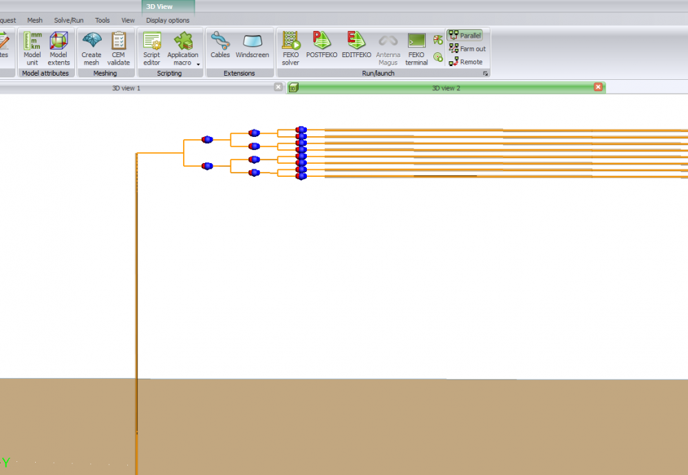
Field-to-Wire-Coupling without Modeling the input and output terminals
i want to study the how the electromagnetic waves couples into multi-transmission line, i have built the circuit shown in the following figure. However, the input and output terminals are effected by the incident wave.
Does there is a way in FEKO so that the input and output terminals are not effected by the wave. i tried to use network schematic but the results was wrong (to build the matrix for the loading is confusing inside network schematic)
any help is appreciated.
thank you
Answers
-
Hi @oussama1
to clarify my understanding of your question - what is the incident waves that you refer to, is the circuit exposed to an external plane wave source? It might help if you attach the .cfx file.
0 -
hello
yes, the structure is exposed to an external plane wave source.
i want to eliminate the effect of the terminals because they have some contribution since the wave can couple to them.
i want to build the structure so that the terminals are outside the field environment. am i able to do that in FEKO
see .cfx file in the attachment
thank you in advance
0 -
hello,
thanks for sharing the additional detail.
I think that your original approach was correct - using general networks. Simulate the S-parameters for the terminal geometry, export the touchstone file and use this in a general network connected to the wires for the simulation with the plane wave.
have a look at the Examples guide for a similar workflow: E-4 Subdividing a model using non-radiating networks
0 -
please can you explain more and show some pictures step by step
because here many student do not know how to do this
thank you
0 -
hello again
i have used the following structure as shown in the attachment file but i have obtained wrong results in the network connection
please i need help as soon as possible
thank you
0 -
hello @Peter Futter
any suggestion, or does there is a way to make the loading wires do not effected by the incident wave
thank you
0 -
hello @oussama1
I was thinking more something like this
Checking the voltage of load 7 you see some differences between the 2 - this could be related to a combination of effects 1) that you want originally wanted to remove (field coupling to the terminals) and 2) also the small ground wires used to connect the terminals to ground for the S-parameter simulations.
0 -
thank you so much
i liked this results, they are amazing
i really appreciate your help
0 -
hello @Peter Futter
your files that you have just sent cannot be opened by my FEKO because it older version, please can you send me here some pictures shows how did you build the model.
for the loads (s-paramters) and the network connection
thank you again
0 -
Hello @oussama1
here are 2 screenshots of the terminal simulation and the network simulation geometry
0 -
hello @Peter Futter
the first one picture is for the terminal ? and the second one for the loads(s-paramters) ?
0 -
Sorry the forum swapped the images around. Image 1) is the 2nd simulation of the long wires including the network block. Image 2) is the S-parameter simulation of the terminals to generate the touchstone file.
0 -
one last question, in s-paramter simulation why did you connect the output terminals to the ground, i really confused about that
thank you so much for your help
0 -
in the first simulation, there is long wires connecting to the ground, i m afraid that the incident field will effect them
0 -
I connected the ports to ground because this is equivalent to how the measurement setup would look. you are welcome to try an open circuit approach.
0 -
thank you so much
what about the long wires that are connected to the ground in the first picture, i think they are effected by the incident field ? is that right ?
0 -
-
1- picture one the whole structure result (correct)
2-picture two the network connection result (wrong)
3-picture three the network connection
4-picture four obtaining the s-parameters of the loading
5-the whole structure connection
any help please
0 -
I cannot tell from the screenshots why you results are different from my results. I would suggest that you update to the latest version of FEKO so that you can open the models that I posted earlier on this discussion
0 -
in your model, you have connected the four wires to the ground, consequently the incident field will couple into them
see your first picture
i want to eliminate all this effects
thank you in advance
0